A spectroscopic measuring device

A spectrum measurement and spectrum technology, which is applied in the field of optical radiation measurement, can solve the problems of large measurement error, stray light and mixing in the measurement device, and achieve the effect of reducing the level of stray light and improving the measurement accuracy

Active Publication Date: 2016-10-12
HANGZHOU EVERFINE PHOTO E INFO
View PDF8 Cites 2 Cited by
  • Summary
  • Abstract
  • Description
  • Claims
  • Application Information

AI Technical Summary

Problems solved by technology

[0004] In traditional spectral measurement devices, aluminum-coated concave mirrors are commonly used imaging components, but aluminum-coated concave mirrors can reflect ultraviolet-visible-infrared light radiation with high reflectivity, such as figure 1 As shown, this broadband reflection characteristic will bring considerable stray light to the spectroscopic measurement device
Taking a typical Czerny-Turner mechanical scanning monochromator as an example, the dispersed light is incident on the converging mirror (aluminized concave mirror), and the scanning mechanism drives the converging mirror to rotate, thereby reflecting different monochromatic light to the exit slit , to realize the scanning of the entire spectrum, due to the overlap of different diffraction order spectra, at the same position of the converging mirror, there may be different diffraction order spectra of the monochromatic light to be measured and other wavelengths at the same time, and the aluminum-coated mirror reflects non-selectively All the light at this position causes a large amount of stray light of other wavelengths to be mixed in besides the monochromatic light to be measured at the exit slit
In addition, for a polychromator using an array detector, light of different wavelengths is received and detected by different pixel areas of the array detector. Since the measurement light and non-measurement light of different wavelengths are reflected by the aluminum-coated concave mirror to the same pixel area, Causes a large amount of stray light from other non-measurement wavelengths to be mixed into the pixel area
Therefore, for a spectral measurement device that uses an aluminum-coated mirror as an imaging element, its non-selective broadband spectral reflection characteristics will bring a large amount of stray light to the measurement device, resulting in large measurement errors

Method used


Image

  • A spectroscopic measuring device
  • A spectroscopic measuring device
  • A spectroscopic measuring device

Examples


Embodiment 1

[0031] Such as Figure 4 As shown, this embodiment discloses a polychromator, including an incident slit 1, a dispersion element 2, an imaging element 3, a spectrally selective film 4 and an array detector. In this embodiment, the dispersion element 2 is a plane grating, the imaging element 3 is a concave mirror, and the spectrally selective thin film 4 coated on the concave mirror 3 is a reflective film.

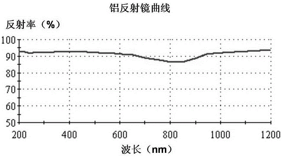
[0032] Such as figure 2 As shown, the spectrally selective reflective film 4 of this embodiment is composed of four reflective films with different selective bands, and the corresponding reflective bands are respectively 350nm-500nm, 450nm-600nm, 480nm-700nm and 500nm-800nm. The reflection bands of the reflective film overlap at the first place, and cover the measurement band of 380nm-780nm of the spectrum measuring device.

[0033] After the incident light is split by the plane grating 2, the monochromatic light of different bands is incident on the concave mirror 3. Si...

Embodiment 2

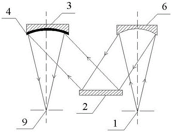
[0036] Such as Figure 5 As shown, this embodiment discloses a monochromator, including an incident slit 1 , a dispersion element 2 , an imaging element 3 , a spectrally selective film 4 , a collimating mirror 6 , an exit slit 9 and a motor 10 . In this embodiment, the dispersion element 2 is a plane grating, the imaging element 3 is a concave reflector, and the spectrally selective film 4 coated on the concave reflector 3 is a reflective film.

[0037] In the actual measurement, the light enters through the incident slit 1, and after being reflected by the collimator 6, it becomes a beam of parallel light incident on the plane grating 2. The plane grating 2 disperses the incident light and projects it on the concave mirror 3, and the concave surface reflects The spectrally selective reflection film 4 on the mirror 3 reflects the corresponding light according to its reflection band, and exits through the exit slit 9 .

[0038] Such as Figure 6 As shown, this embodiment also...

Embodiment 3

[0040] Such as Figure 7 As shown, this embodiment discloses a double monochromator, including an incident slit 1, two dispersive elements 2, two imaging elements 3, a spectrally selective film 4, four mirrors 7, and two collimating mirrors 6, and exit slit 9. The two dispersion elements 2 in the present embodiment are all planar gratings, and the two imaging elements 3 are all concave reflectors with the same structure and size, and the spectrally selective thin films 4 plated on the concave reflector 3 are reflective films. The spectrum selective reflection film 4 on the concave reflector 3 in the example is as figure 2 As shown, the selected wavelength band is the same as that in Embodiment 1, and the corresponding positions of the reflective film on the two concave reflectors 3 are exactly the same.

[0041] During measurement, the light enters through the incident slit 1, and after being reflected by the reflector 7, it is reflected by the collimator 6 as a beam of par...


PUM


Abstract

The invention discloses a spectral measurement device, comprising optical elements including an incidence slit, a dispersing element and an imaging element. A spectral selection thin film is plated on the surface of each optical element; the selection wave band of the spectral selection thin film corresponds to a measurement wave band of the spectral measurement device; the optical elements plated with the spectral selection thin film only can emit light within the selection wave band of the spectral selection thin film so as to greatly weaken light with other wavelengths in a light path, Thus the stray light level of an optical system is greatly reduced.

Description

technical field [0001] The invention belongs to the field of optical radiation measurement, and in particular relates to a spectrum measurement device. Background technique [0002] The spectral measurement device is an optical instrument used to measure the spectral power distribution of illuminants, and is widely used in light source radiation measurement, color measurement, element identification, chemical analysis and other fields. Spectrum measurement devices include various types, which are divided into vacuum ultraviolet / ultraviolet / visible light / near-infrared / infrared / far-infrared spectrometers according to the spectral range they can work normally; Interference spectrometer, etc.; according to different detection methods, it is divided into spectrometer, spectrograph and photoelectric spectrometer, etc.; according to the function and structural characteristics of the device, it is divided into monochromator (grating / prism / double monochromator, etc.) and multi- Colo...

Claims


Application Information

Patent Timeline
Patent Type & Authority Patents(China)
IPC IPC(8): G01J3/28G01J3/02
Inventor 潘建根
Owner HANGZHOU EVERFINE PHOTO E INFO
Why Eureka
Try Eureka