A scanning laser radar optical system

An optical system and laser radar technology, applied in the field of laser radar optical system, can solve the problems of low signal-to-noise ratio, small array, missing signals, etc., and achieve the effect of improving signal-to-noise ratio and reducing stray light level

Inactive Publication Date: 2019-04-26
CHANGCHUN UNIV OF SCI & TECH
View PDF7 Cites 0 Cited by
  • Summary
  • Abstract
  • Description
  • Claims
  • Application Information

AI Technical Summary

Problems solved by technology

The invention patent with the patent number CN102338875B is a multi-line scanning forward-looking anti-collision lidar device and its application and the invention patent with the patent number CN101776760A is a laser three-dimensional imaging device based on a single-photon detector, all of which are scanned by the laser radar The laser emitting system can scan synchronously with the laser receiving system, but this requires a relatively large scanning mechanism. When the laser emitting system scans independently and the laser receiving system is fixed, two solutions can be used. One is the invention with the patent number CN105044731A Patented a laser three-dimensional imaging system and imaging method, based on a two-dimensional array detector, the receiving field of view is divided, and only the incident light in the scanning point area includes laser reflected light and background light, but the two-dimensional array detection of the pulse signal can be measured The array of the sensor is small, the cost is high, and there is a non-sensitive area between the pixels, which will miss the signal; the other is based on a single-point detector, which receives all the incident light in the scanning range. When the scanning field of view is large or the background light When strong, the signal-to-noise ratio of the detection is low

Method used


Image

  • A scanning laser radar optical system
  • A scanning laser radar optical system
  • A scanning laser radar optical system

Examples


Embodiment Construction

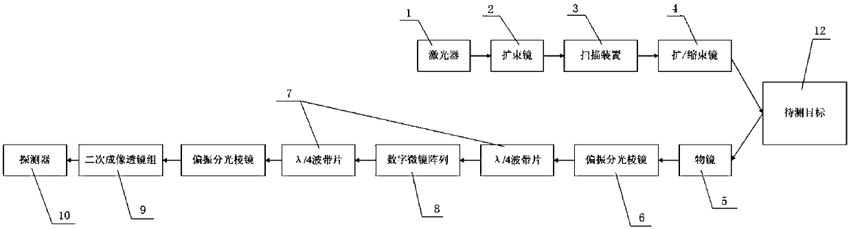
[0016] A scanning laser radar optical system, such as figure 1 and figure 2 As shown, it includes a laser emitting optical system and a laser receiving optical system. The laser emitting system includes a laser 1, a beam expander 2, a scanning device 3, and a beam expander / shrinker 4. The laser 1 generates polarized pulsed laser light;

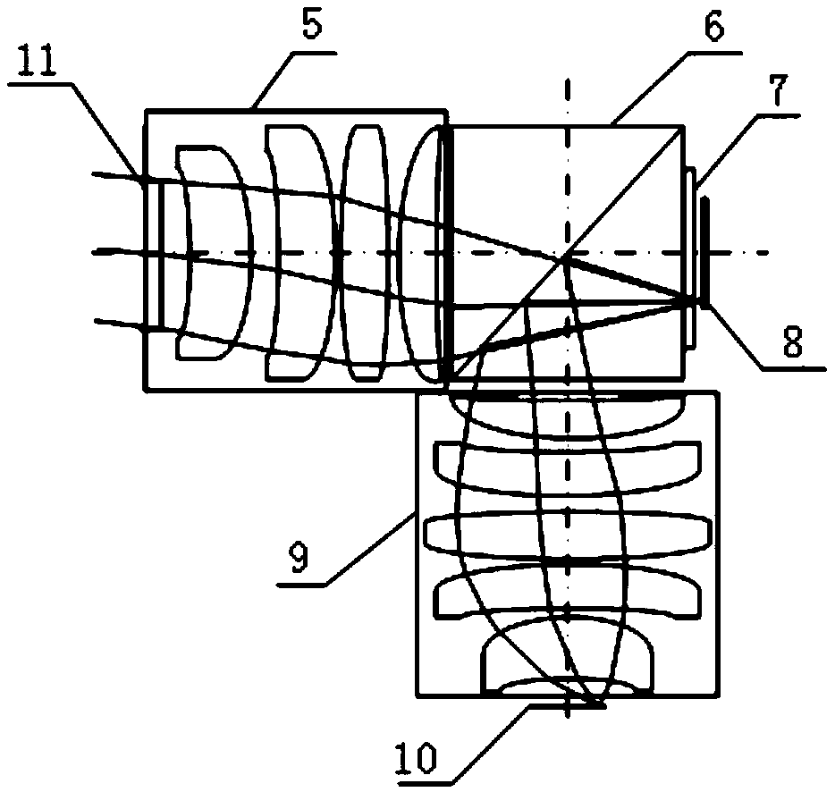
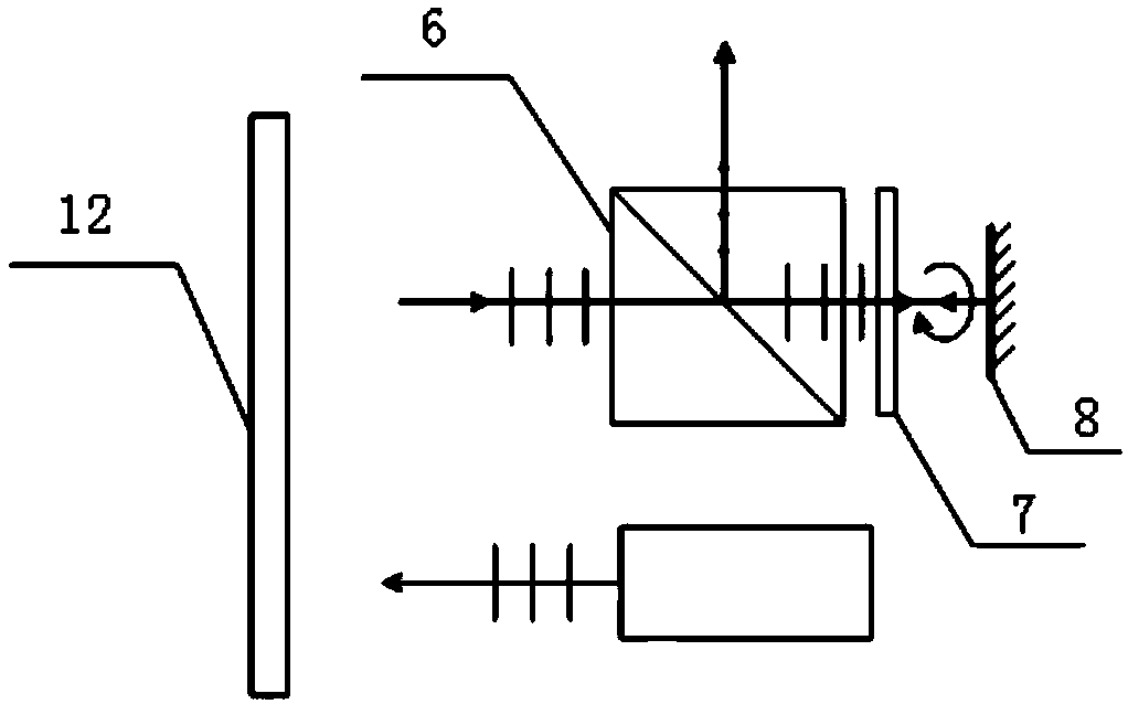
[0017] The laser receiving optical system includes a narrow-band filter 11, an objective lens 5, a polarization beam splitter prism 6, a λ / 4 zone plate 7, a digital micromirror array 8, a secondary imaging lens group 9, and a detector 10. The narrow-band filter 11 is Before, next is the objective lens 5, the polarization beam splitter prism 6, the λ / 4 zone plate 7, the digital micromirror array 8, the secondary imaging lens group 9 is above the polarization beam splitter prism 6, and the detector 10 is in the secondary imaging lens group 9 Above; the laser receiving optical system narrow-band filter 11 filters the stray light outside the las...


PUM


Abstract

The invention provides a scanning-type laser radar optical system, and belongs to the technical field of laser radar scanning. The system comprises a laser emitting optical system and a laser receiving optical system. The laser emitting optical system comprises a laser, a beam expanding mirror, a scanning device and a beam expanding / shrinking lens. The laser 1 generates a linearly polarized pulsed laser. The laser passes through the beam expanding lens to shoot onto the scanning device. After shooting out of the scanning device, the laser shoots onto the beam expanding / shrinking lens and then is pointed onto a to-be-detected target after shooting out of the beam expanding / shrinking lens. The laser receiving optical system comprises an objective lens, a polarization splitting prism, a digital micro-mirror array, a secondary imaging lens set, a detector, a narrow-band filter and a lambda / 4 waveband plate. The system can be applied to large-view-field laser radars or strong-background-light detection conditions in the field of view.

Description

technical field [0001] The invention belongs to the technical field of laser radar scanning, and in particular relates to a laser radar optical system. Background technique [0002] Laser imaging radar is the product of the combination of traditional radar technology and modern laser technology. It can collect azimuth-pitch angle-distance three-dimensional data and display the data in the form of images. Scanning imaging laser radar technology has evolved from the simplest laser ranging technology. In the beginning, the 3D detection of the target is realized by 2D scanning. It has a series of advantages such as high angular resolution, high distance resolution, strong anti-interference ability, small size and light weight. The scanning laser radar emits a laser pulse beam that hits the target object and reflects it back. The receiver accurately measures the propagation time difference of the light pulse from emission to reflection. If the speed of light is known, the distan...

Claims


Application Information

Patent Timeline
Patent Type & Authority Patents(China)
IPC IPC(8): G01S17/89G01S7/481
CPCG01S7/4817G01S17/89
Inventor 刘壮江伦王超佟守峰李英超安岩
Owner CHANGCHUN UNIV OF SCI & TECH
Why Eureka
Try Eureka