Device for testing insertion and withdrawal forces of contact elements of electric connectors in high temperature environments

A technology for electrical connectors and high-temperature environments. It is applied in the field of insertion and extraction force testing. It can solve the problems that the measurement results of insertion and extraction force are greatly affected, the precise alignment of contacts cannot be guaranteed, and the separation speed and insertion amount cannot be accurately controlled. Achieve the effects of convenient operation, reduced impact, accurate and reliable test results

Inactive Publication Date: 2012-09-19
ZHEJIANG SCI-TECH UNIV
View PDF6 Cites 36 Cited by
  • Summary
  • Abstract
  • Description
  • Claims
  • Application Information

AI Technical Summary

Problems solved by technology

[0005] 1. Measuring the insertion and withdrawal force at room temperature cannot really simulate the actual working conditions of the contacts, and cannot fully consider the influence of high temperature on the insertion and withdrawal force; using the test results at room temperature to replace or infer the insertion and withdrawal force at high temperature cannot reflect the reality Happening
[0006] 2. The existing test methods mostly use manual plugging and unplugging, which cannot accurately control the separation speed and insertion amount, and cannot ensure the precise alignment of the contacts when plugging and unplugging. Human factors have a greater impact on the measurement results of the plugging force
[0007] 3. The insertion and withdrawal force of the electrical connector is not only related to temperature, but also closely related to the number of insertions and extractions (mechanical life). Insert and unplug and check the change of insertion force

Method used


Image

  • Device for testing insertion and withdrawal forces of contact elements of electric connectors in high temperature environments
  • Device for testing insertion and withdrawal forces of contact elements of electric connectors in high temperature environments

Examples


Embodiment Construction

[0026] In order to make the object, technical solution and advantages of the present invention clearer, the present invention will be further described in detail below in conjunction with the accompanying drawings. It should be understood that the specific embodiments described here are only used to explain the present invention, not to limit the present invention.

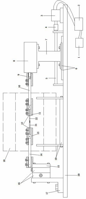
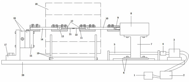
[0027] As shown in the figure, the present invention provides a device for testing the insertion and withdrawal force of electrical connector contacts in a high temperature environment. The electrical connector contacts include sockets 21 and pins 22. The test device includes: The left mechanical clamping device with heat insulation function for socket 21, the right mechanical clamping device with heat insulation function for clamping pin 22, the force measuring device 8 for testing the insertion and withdrawal force of contacts, and the The mechanical transmission device that drives the force measuring device 8 t...


PUM


Abstract

The invention discloses a device for testing insertion and withdrawal forces of contact elements of electric connectors in high temperature environments, which comprises a left mechanical clamping device, a right mechanical clamping device, a force testing device, a mechanical drive device, a driving device, an adjusting platform and an electromagnetic induction heating device, wherein the left mechanical clamping device is used for clamping a jacks and has a heat insulation function, the right mechanical clamping device is used for clamping inserting pins and has a heat insulation function, the force testing device is used for testing insertion and withdrawal forces of contact elements, the mechanical drive device is used for driving the force testing device to carry out a reciprocating motion, the driving device is used for driving the mechanical drive device, the adjusting platform is used for adjusting the alignment accuracy of a contact element, and the electromagnetic induction heating device is used for simulating the temperature of a working environment. A contact element is heated to a specified temperature by using the electromagnetic induction heating device; the driving device drives the right mechanical clamping device to move through the mechanical drive device so as to realize the insertion and withdrawal motions of the contact element; and then the force testing device acquires data. Through adopting a method for testing insertion and withdrawal forces of contact elements directly in high temperature environments, the device can truly respond to the operating situations of the contact element at high temperature, therefore, the device is suitable to be used in various electric connector factories and research institutions, and ensures the accuracy of measured data.

Description

technical field [0001] The invention belongs to the field of insertion and extraction force testing, and in particular relates to a testing device for the insertion and extraction force of electrical connector contacts (generally referring to pins and jacks) in high temperature environments. Background technique [0002] As a basic component, the electrical connector's main function is to realize the circuit, signal conduction and control between various components, circuits, equipment, systems, etc. It has a wide range of applications in aviation, aerospace, communication, electromechanical and other industries. The number is considerable and the status is important. With the development of my country's new generation of weapons and delivery technology, especially the development of high-speed and ultra-high-speed cruise missiles and large launch vehicles, it is required that the system can work normally in a complex space environment and electromagnetic environment. The el...

Claims


Application Information

Patent Timeline
Patent Type & Authority Applications(China)
IPC IPC(8): G01L5/00G01M13/00
Inventor 潘骏靳方建陈文华贺青川杨帆许锐敏刘东旭朱旭洋王孟
Owner ZHEJIANG SCI-TECH UNIV
Why Eureka
Try Eureka