Steel ball surface defect detection automatic sorting device

A defect detection and automatic sorting technology, applied in the field of defect detection, can solve problems such as the inability to guarantee the full expansion of the spherical surface, the inability to guarantee full expansion, and the addition of degaussing steps, so as to achieve a high degree of detection automation, accurate and efficient defect detection, and improved detection The effect of the rate

Inactive Publication Date: 2012-09-19
TIANJIN UNIV
View PDF8 Cites 35 Cited by
  • Summary
  • Abstract
  • Description
  • Claims
  • Application Information

AI Technical Summary

Problems solved by technology

The unfolding device of this method is complicated, and the unfolding is random, which cannot guarantee the complete unfolding of the spherical surface; the immersion in the liquid will cause certain stains on the steel ball itself, and the collected images are prone to impurities that affect the evaluation, not only need to be replaced regularly, but also increase the follow-up cleaning steps; The range of detection balls is large and medium-sized steel balls, not suitable for miniature steel balls below 3mm
The Chinese invention patent with the patent number ZL200910040283.1 has developed visual small ball defect detection equipment and methods for miniature steel balls, but the ball surface of the detection position is unfolded on the premise that no slippage is still relied on the pallet to rub the bottom, which cannot be guaranteed Fully deployed; the sorting mechanism adopts magnetic suction to remove defective balls, which may easily cause steel balls to be magnetized, and degaussing steps need to be added later; the sorting mechanism is complicated and the detection efficiency is low

Method used


Image

  • Steel ball surface defect detection automatic sorting device
  • Steel ball surface defect detection automatic sorting device
  • Steel ball surface defect detection automatic sorting device

Examples


Embodiment Construction

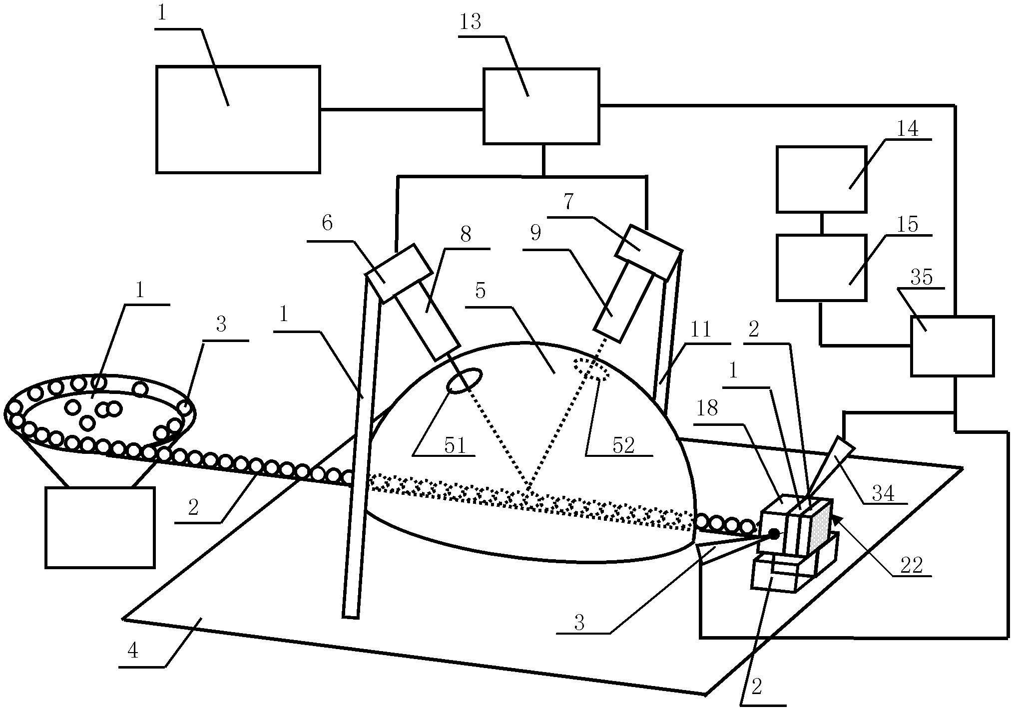
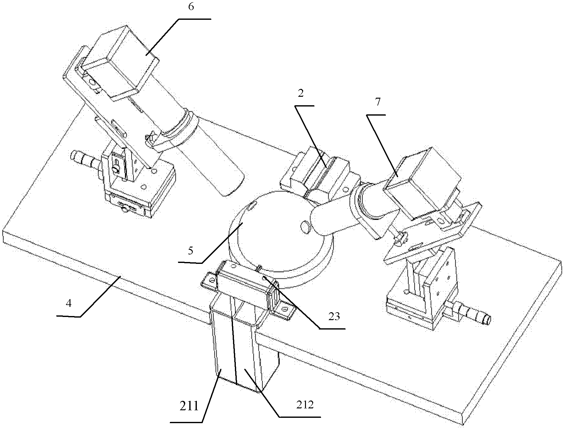
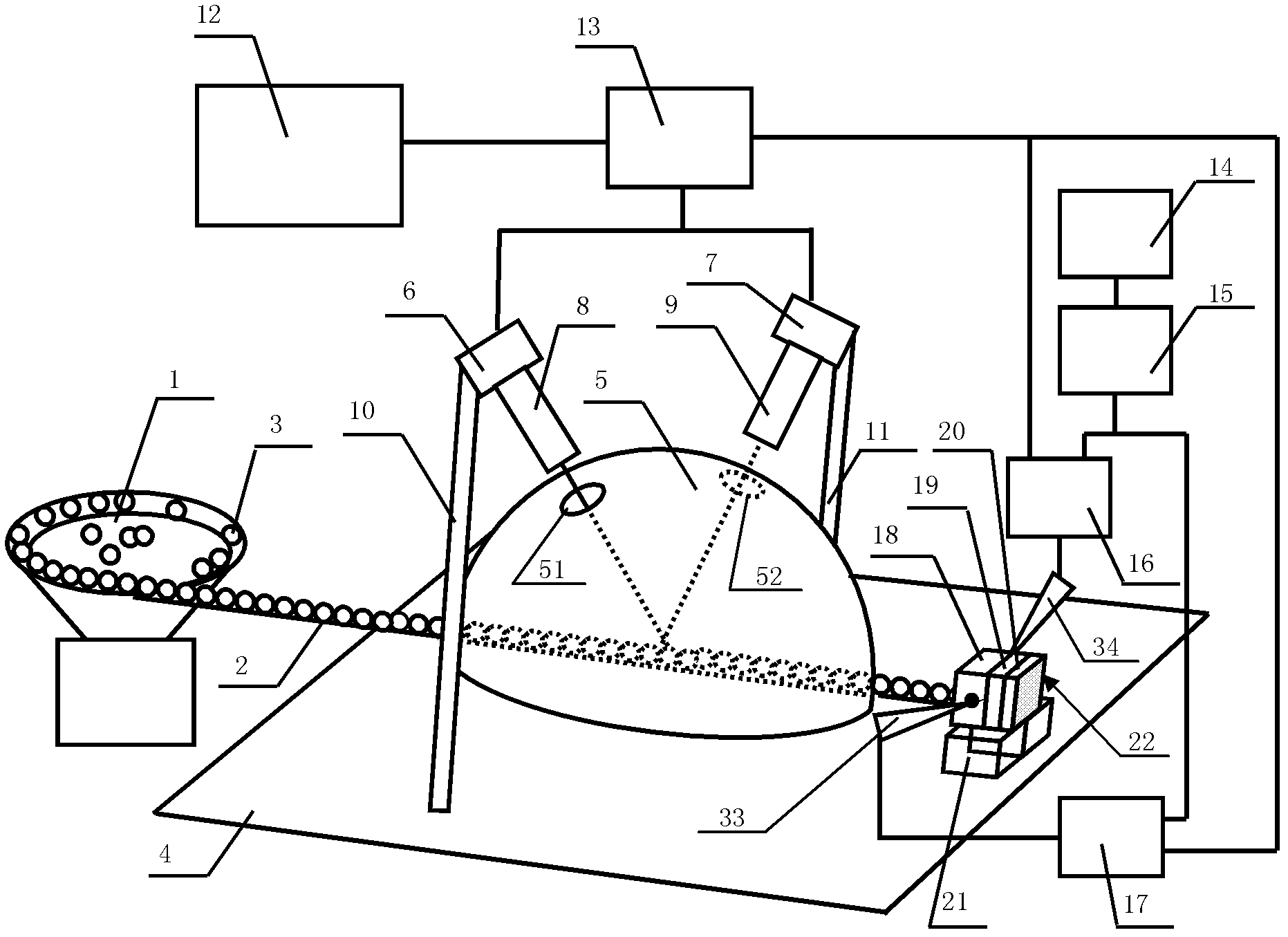
[0053] The steel ball surface defect detection and automatic sorting device of the present invention will be described in detail below in conjunction with the embodiments and accompanying drawings.

[0054] Such as figure 1 , figure 2 , image 3 As shown, the steel ball surface defect detection automatic sorting device of the present invention includes a workbench 4, and the workbench 4 is provided with a light source 5 composed of a light source bowl cover and an LED light source covered in the light source bowl cover. The light source described above adopts a diffuse reflection dome-shaped LED light source. The left and right sides of the light source bowl cover are symmetrically provided with a left bracket 10 and a right bracket 11, the left side camera 6 is installed on the left bracket 10, and the right side camera 6 having the same structure as the left side camera 6 is installed on the right bracket 11. The camera 7, the lens 8 of the left camera 6 and the lens 9 o...


PUM


Abstract

Disclosed is a steel ball surface defect detection automatic sorting device. A light source is arranged on a work bench, a left camera mounted on a left support and a right camera mounted on a right support are symmetrically arranged on the left side and the right side of a light source bowl cover, camera lenses of the left camera and the right camera are arranged symmetrically and corresponding to a left observation hole and a right observation hole formed on the light source bowl cover, a vibration feed table and a material transferring channel connected to a discharge hole of the vibration feeding table are arranged behind the light source, the material transferring channel penetrates through the power source bowel cover and the front of the light source, a sorting mechanism and a collecting box placed below the sorting mechanism are arranged in front of the light source, a discharge terminal of the material transferring channel is inserted into a feeding hole end of the sorting mechanism, the left camera and the right camera are respectively connected with a peripheral component interconnection (PCI) card, PCI cards are respectively connected with a computer and a pneumatic unit, and an output end of the pneumatic unit is connected with the sorting mechanism. According to the steel ball surface defect detection automatic sorting device, the detecting process can achieve automation completely, no easily-worn part exists, the service life is long, and defect detection is accurate and efficient.

Description

technical field [0001] The invention relates to the field of defect detection. In particular, it relates to a vision-based automatic sorting device for steel ball surface defect detection. Background technique [0002] Steel balls are widely used both as bearing balls and as general-purpose rolling elements. The surface quality of the steel ball directly affects the precision and service life of the bearing. At present, most of the domestic steel ball production enterprises adopt the traditional light inspection method, that is, the personnel manually move the steel ball in the flat shovel, observe it with the naked eye (or a low-power magnifying glass) under the light, and manually pick out the steel ball. defective ball. In the face of batch inspection requirements, the light inspection method is not only low in detection efficiency, but also cannot ensure that the ball surface is fully expanded by manual pushing, which is easy to miss or falsely detect, and at the same...

Claims


Application Information

Patent Timeline
Patent Type & Authority Applications(China)
IPC IPC(8): G01N21/89B07C5/02B07C5/36
Inventor 王仲栗琳裴芳莹赵志
Owner TIANJIN UNIV
Why Eureka
Try Eureka