Novel phase shifting rectifier transformer

A technology of rectifying transformers and phase shifting, applied in transformers, fixed transformers, variable transformers, etc., can solve the problems of complex structure of oil tanks and lead wires, selection of phase shifting angles, and high difficulty in implementation, so as to achieve low implementation difficulty, reduce equipment manufacturing, and Guarantee the effect of product performance

Active Publication Date: 2012-09-19
北海银河生物产业投资股份有限公司
View PDF6 Cites 8 Cited by
  • Summary
  • Abstract
  • Description
  • Claims
  • Application Information

AI Technical Summary

Problems solved by technology

[0004] 1. The voltage regulating rectifier transformer has been connected at the factory, that is, the phase shift angle (including positive and negative polarity) of each voltage regulating rectifier transformer is fixed, that is, each voltage regulating rectifier transformer corresponds to only one set of phase shift angles , there is no way to choose its phase shift angle according to the needs; if it is difficult to change on site, it is even impossible to realize;
[0005] 2. The terminals of the phase-shifting winding of the voltage regulating rectifier transformer are all connected to the junction box on the box wall. When the phase-shifting angle needs to be changed, the wiring should be changed (only refers to changing the positive and negative polarity of the phase-shifting angle). If the wiring is changed in the junction box, it will take up The space is large, the structure of the fuel tank and lead wires is complex, especially for high voltage levels, the implementation is difficult, and sometimes it is even impossible to implement

Method used


Image

  • Novel phase shifting rectifier transformer
  • Novel phase shifting rectifier transformer
  • Novel phase shifting rectifier transformer

Examples


Embodiment 1

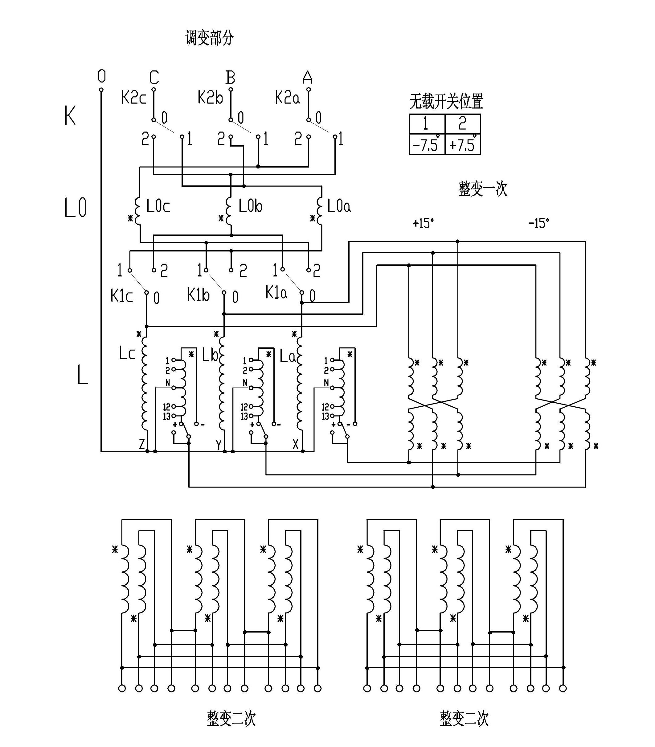
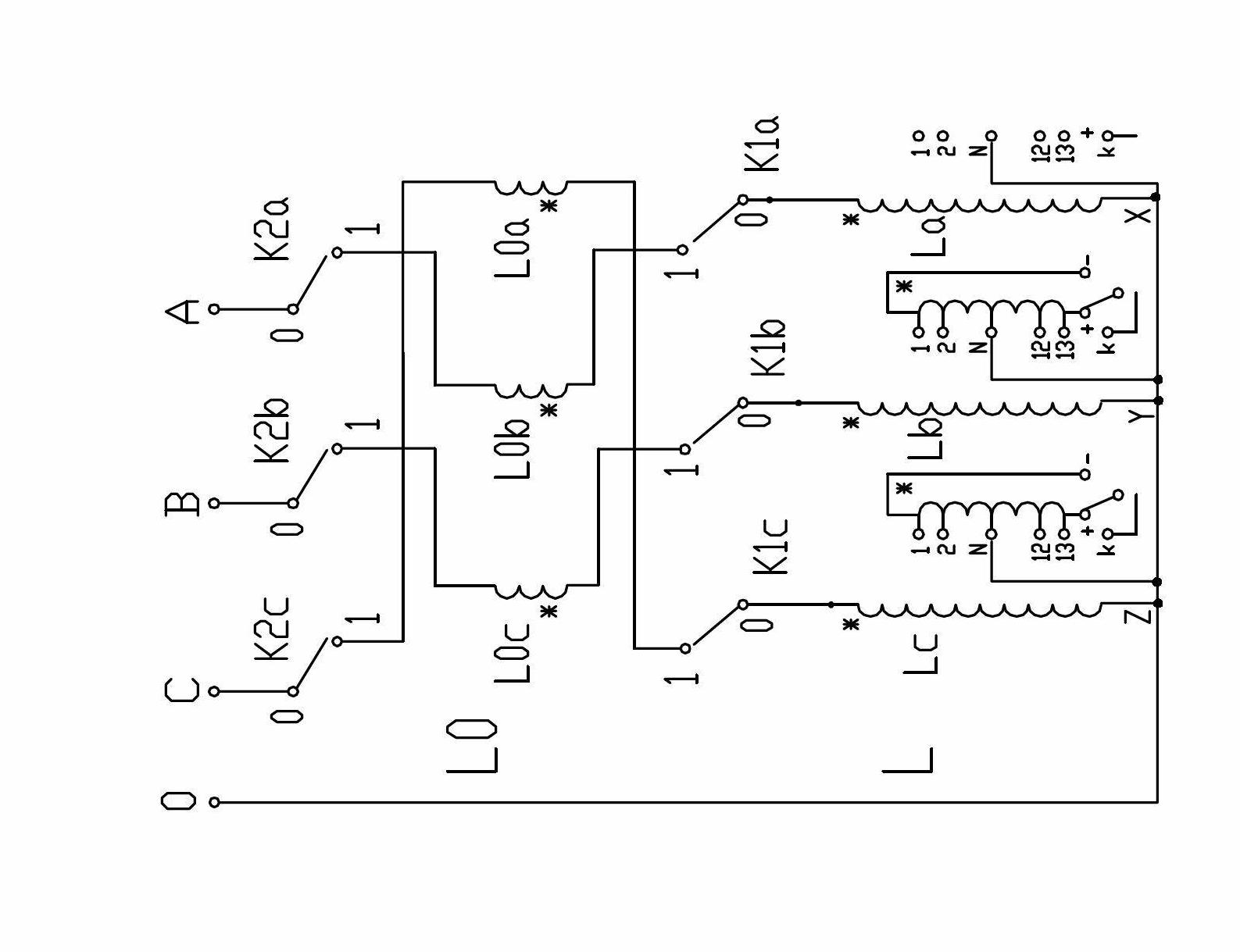
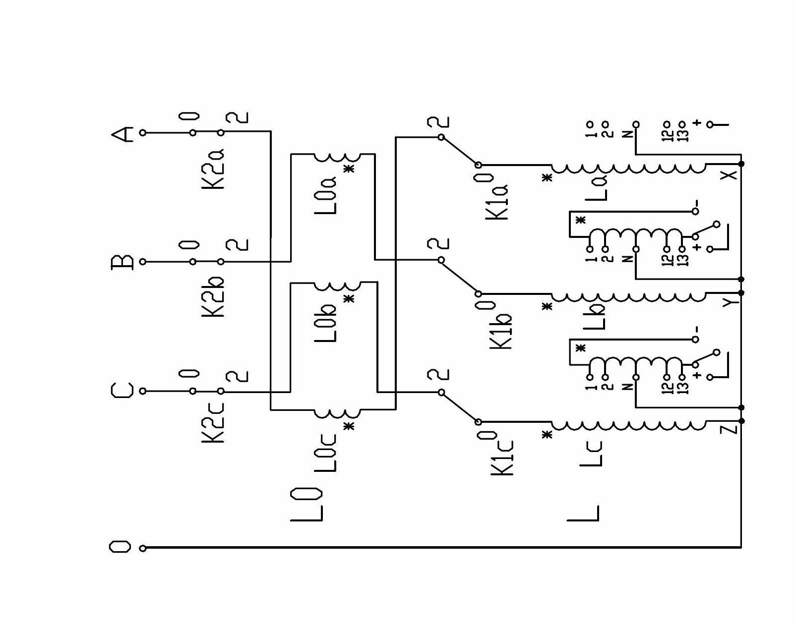
[0032] Design requirements: The entire rectifier unit has two voltage-regulating rectifier transformers, model ZHSSPT-20000 / 63, requiring two voltage-regulating rectifier transformers to operate in parallel, with a single 12-pulse wave, and two sets of equivalent 24-pulse waves, and another one with the same The transformer of the model is used as a backup, and the design scheme is a one-to-two structure, that is, one voltage regulating and rectifying transformer includes a modulator body and two rectifier bodies, the modulating side adopts zigzag phase shifting, and the two modulating rectifiers The phase angles are +7.5° and -7.5° respectively; the primary side of the rectification adopts zigzag phase shifting, the phase shifting angles of the two rectifier bodies are respectively +15° and -15°, and the secondary rectification is triangular wiring. In this way, two voltage regulating rectifier transformers form an equivalent 24-pulse wave.

[0033] The scheme of the present...

Embodiment 2

[0044] Design requirements: The entire rectifier unit has three voltage-regulating rectifier transformers, model ZHSSPT-16000 / 35, and the user requires another transformer of the same type as a backup. These three voltage-regulating rectifier transformers operate in parallel. Composing equivalent 36 pulse waves, the design scheme is a one-to-two structure, that is, one voltage regulating rectifier transformer includes one modulator body and two rectifier bodies, the modulating side adopts zigzag phase shifting, and three modulating rectifiers The phase shift angles are +10°, 0° and -10° respectively; the primary side of the rectification adopts zigzag phase shift, and the phase shift angles of the two rectifier bodies are respectively +15° and -15°, and the rectification secondary The times are all triangle connections, so that the three voltage regulating rectifier transformers form an equivalent 36-pulse wave.

[0045] Scheme of the present invention: see attached Figure 4...

Embodiment 3

[0058] Design requirements: The entire rectifier unit has three voltage-regulating rectifier transformers, model ZHSSPT-25000 / 35, and the user requires that they be put into operation in two phases. In the first phase, two sets will be put into operation first, and the entire unit will form an equivalent 24-pulse wave; After running in parallel with the two units in the first phase, the whole unit constitutes an equivalent 36-pulse wave, and the design scheme is a one-to-two structure, that is, a voltage regulating rectifier transformer includes a regulator body and two rectifier bodies, and the modulation side Zigzag phase-shifting is adopted. The phase-shifting windings of the two modulators in the first phase are designed to have angle taps of +10°, +7.5°, 0°, -7.5° and -10°. Use no phase shift (that is, phase shift 0°).

[0059] The scheme of the present invention is: see attached Figure 8 , a new type of phase-shifting rectifier transformer, including a modulator body, ...


PUM


Abstract

The invention discloses a novel phase shifting rectifier transformer, which comprises a voltage regulating transformer body, a rectifier transformer body and a phase shifting unit. The phase shifting unit is arranged on a voltage regulating transformer side, and comprises a phase shifting coil and a no-load switch. The no-load switch comprises an input stage and an output stage. A common joint of the output stage is a phase shifting leading-out end, and a common joint of the input stage is directly connected with the leading-out end of a basic winding of a voltage regulating transformer coil, or is connected with the leading-out end of the basic winding of the voltage regulating transformer coil through a no-load reversing switch. Dotted terminals and unlike terminals or the dotted terminals, the unlike terminals and tap joints of the phase shifting coil are respectively connected with gear joints of the input and output stages of the no-load switch, and phase shifting in different angles is realized through the transformation of different gears of the no-load switch or the no-load switch and the no-load reversing switch. The rectifier transformer is simple in structure, low in construction difficulty and convenient to operate, occupies a small space, and can be easily implemented even at a high voltage level. The performance of the product can be ensured, production efficiency can be improved, the manufacture, operation and maintenance cost of equipment is lowered, and the effects of energy saving and consumption reduction are achieved.

Description

technical field [0001] The invention relates to the field of special transformers, in particular to a novel phase-shifting rectifier transformer. Background technique [0002] In high-power rectification equipment, 12-pulse wave can no longer meet the requirements, and a rectifier unit with a larger pulse number must be used. In this case, two or more voltage regulating and rectifying transformers must be operated in parallel. Such voltage regulating and rectifying transformers must be equipped with special phase-shifting windings for phase shifting. The phase-shifting windings are usually set at the following positions: 1. On the primary side of the rectifier transformer (see attached Figure 9 ); 2. Simultaneously set on the side of the voltage regulating transformer and the primary side of the rectifier transformer (see attached Figure 10 ). [0003] There is following deficiency in above-mentioned two schemes: [0004] 1. The voltage regulating rectifier transformer...

Claims


Application Information

Patent Timeline
Patent Type & Authority Applications(China)
IPC IPC(8): H01F30/06H01F29/02H01F27/28H01F27/40
Inventor 玉增友王涛陈天平阮势伟
Owner 北海银河生物产业投资股份有限公司
Why Eureka
Try Eureka