Quasi-isostatic pressing vacuum hydraulic machine

A quasi-isostatic hydraulic press technology, applied in the field of hydraulic equipment, can solve the problems of lack of air extraction function and difficult structural design of quasi-isostatic hydraulic press, and achieve the effect of convenient operation and compact structure

Active Publication Date: 2012-09-26
TSINGHUA UNIV
View PDF5 Cites 20 Cited by
  • Summary
  • Abstract
  • Description
  • Claims
  • Application Information

AI Technical Summary

Problems solved by technology

The quasi-isostatic hydraulic press with vacuum function is also a d...

Method used


Image

  • Quasi-isostatic pressing vacuum hydraulic machine
  • Quasi-isostatic pressing vacuum hydraulic machine
  • Quasi-isostatic pressing vacuum hydraulic machine

Examples


Embodiment 1

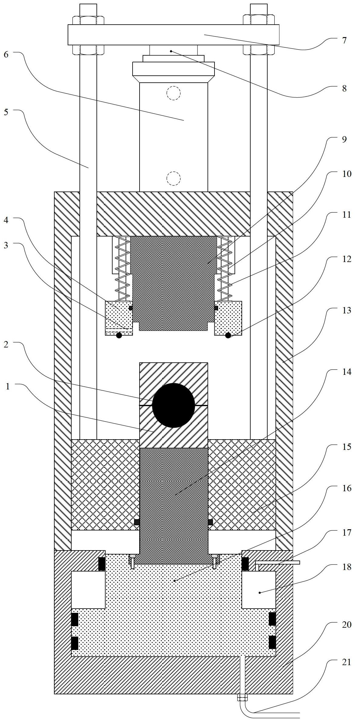
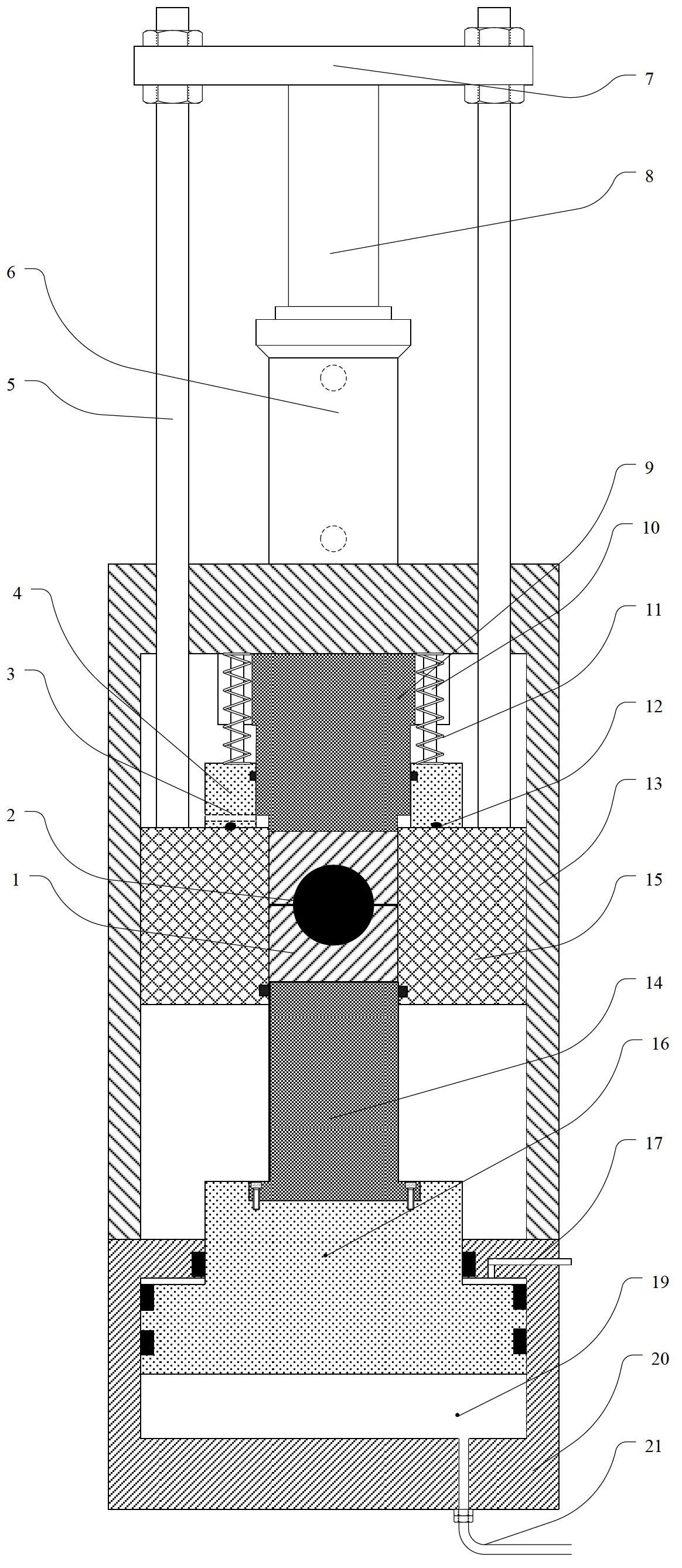
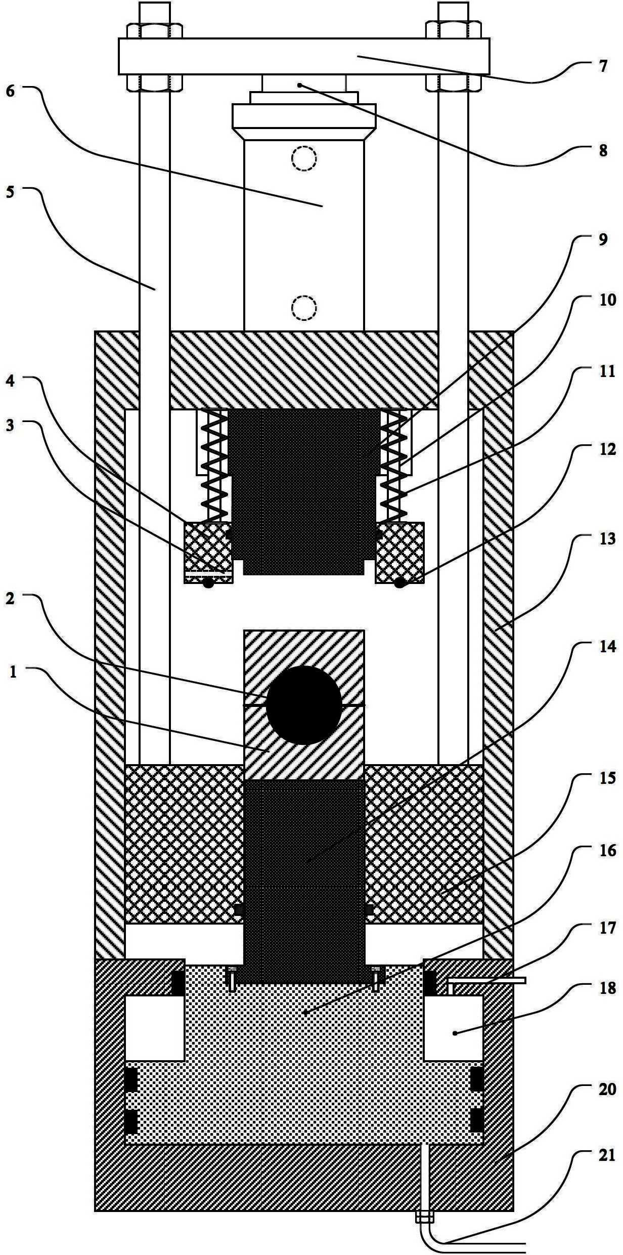
[0025] The quasi-isostatic vacuum hydraulic machine disclosed in this embodiment includes a main body, a hydraulic transmission system, a vacuum system and an electrical control system.

[0026] Such as figure 1 with figure 2 As shown, the main body mainly includes the fuselage 13, the lower main hydraulic cylinder 20, the upper auxiliary hydraulic cylinder 6, the upper punch 9, the lower punch 14, the vacuum cover 4 and the steel mold cylinder 15, all of which are on the same axis heart line.

[0027] The fuselage 13 is the part for pressing and operating, and is fastened on the lower main hydraulic cylinder 20 by screws or other means to form a closed rigid integral frame. Fuselage 13 The body is a cavity with an operation window on the side, and the shape is preferably cylindrical. The upper punch 9, the lower punch 14, the vacuum cover 4 and the steel mold barrel 15 are all installed inside the body 13 cavity. The lower punch 14 is fixed on the upper end of the main h...

Embodiment 2

[0032] When the vacuum hydraulic press described in Embodiment 1 of the present invention works, it operates as follows:

[0033] Place the rubber mold 1 equipped with the prepared powder 2 on the lower punch 14;

[0034] The auxiliary hydraulic cylinder 6 works, the piston rod 7 goes up, and the steel mold cylinder 15 is driven up by the load beam 8 and the guide rod 5 until it is closely attached to the vacuum cover 4;

[0035] The vacuum system is opened, and the space formed by the vacuum cover 4, the upper punch 9, the lower punch 14, and the steel mold cylinder 15 is vacuumed through the air extraction hole 3;

[0036] When the vacuum degree reaches the set value, the main hydraulic cylinder 20 works, and the hydraulic system injects hydraulic oil into the lower chamber 19 of the main hydraulic cylinder through the oil pipe 21 in the lower chamber of the main hydraulic cylinder, so that the piston 16 of the main hydraulic cylinder drives the lower punch 14 to move upward...


PUM


Abstract

The invention relates to the field of hydraulic equipment, in particular to a quasi-isostatic pressing vacuum hydraulic machine. The hydraulic machine comprises a main machine body, a hydraulic transmission system, a vacuum system and an electric control system, wherein the main machine body comprises a machine body, a lower main hydraulic cylinder, an upper auxiliary hydraulic cylinder, a lower punch, an upper punch, a steel die barrel and a vacuum cover; the machine body is connected to the lower main hydraulic cylinder; the auxiliary hydraulic cylinder is arranged on the machine body; the lower punch is fixed at the upper end of a piston of the main hydraulic cylinder and can move together with the piston of the main hydraulic cylinder under the guidance of the internal surface of the steel die barrel; the upper punch is fixed below the plane on the top of an inner cavity of the machine body; the steel die barrel and the vacuum cover are arranged in the cavity of the machine body; and the vacuum cover is connected with the top of the inner cavity of the machine body through a sliding column and a spring and can passively ascend along the sliding column under the push of the steel die barrel and passively descend under the reset action of the spring. The quasi-isostatic pressing vacuum hydraulic machine can press a rubber die in a vacuum state, has the characteristic of compact structure and is convenient to operate.

Description

technical field [0001] The invention relates to the field of hydraulic equipment, in particular to a quasi-isostatic vacuum hydraulic press used for element ball final pressure in the manufacture of high-temperature gas-cooled reactor fuel elements. Background technique [0002] The diameter of the spherical fuel element used in the pebble bed high-temperature gas-cooled reactor in my country is 60mm, and the whole is a graphite matrix. The outer layer is a fuel-free area with a thickness of about 5mm, and the interior is the fuel of spherical coated particles (TRISO) dispersed in the graphite matrix. Area. In order to ensure the isotropy of the component ball, it is necessary to adopt isostatic pressing or quasi-isostatic pressing molding process. The above-mentioned spherical fuel element is manufactured by the soft mold quasi-isostatic pressing process (Atomic Energy Science and Technology, 2003, vol37, 40-44). Soft mold pressing is a quasi-isostatic pressing process tha...

Claims


Application Information

Patent Timeline
IPC IPC(8): B30B5/02B30B15/00
CPCB30B15/024
Inventor 张杰卢振明周湘文邹彦文刘兵唐亚平
Owner TSINGHUA UNIV
Why Eureka
Try Eureka