Fastening system

A technology for fixing systems and fixing components, which can be used in threaded fasteners, light impact tools, turning equipment, etc., and can solve problems such as thread damage

Active Publication Date: 2012-09-26
HILTI AG
View PDF10 Cites 0 Cited by
  • Summary
  • Abstract
  • Description
  • Claims
  • Application Information

AI Technical Summary

Problems solved by technology

However, since the fixing element itself takes part in the formation of the drilled hole,

Method used


Image

  • Fastening system
  • Fastening system
  • Fastening system

Examples


Embodiment Construction

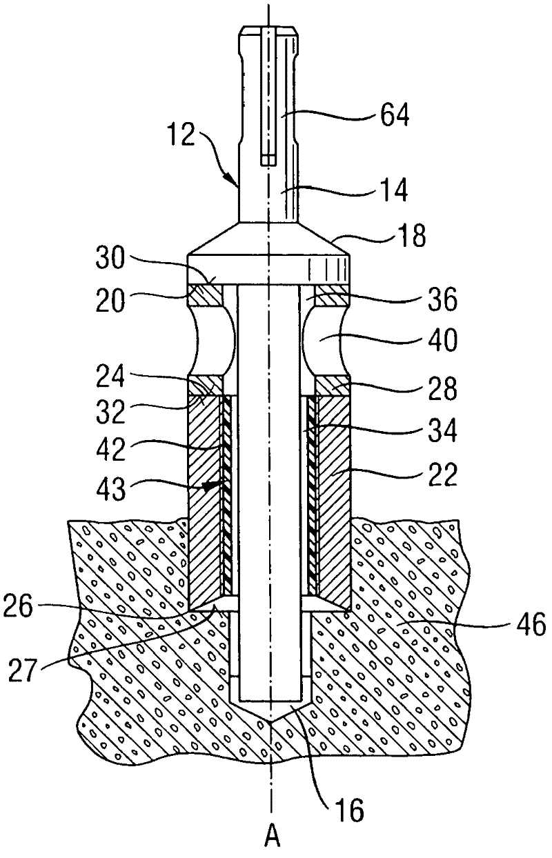
[0038] figure 1 A fastening system 10 is shown with a drill head 12 having a drill rod 14 and a drill tip 16 . A radially protruding shoulder 18 is formed on the drill rod 14 in the upper section, which shoulder has a substantially horizontal impact surface 20 facing the drill point 16 .

[0039] Arranged below the impact surface 20 is a fastening element 22 which is sleeve-shaped and surrounds the drill rod 14 concentrically, and has an essentially horizontal impact surface 24 facing the impact of the shoulder 18 . Surface 20. Both impact surfaces have a deviation from perpendicular to the axial direction A of at most 3°.

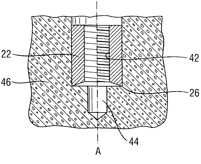
[0040] At the axial end facing away from the impact surface 24 , the fastening element 22 has a cutting edge 26 that is as sharp as possible. A front disintegration surface 27 of the disintegration base material adjoins radially inwardly on the cutting edge 26 .

[0041] The fastening element 22 is formed here from a material in which at least the impa...


PUM


Abstract

The mounting system comprises a driller (12) and a sleeve-like mounting element (22), which has a cutting edge (26) and a striking surface (24). The mounting element is acted upon by axially acting forces over the striking surface. The mounting element has an axial passage opening (34) with an internal thread (42), through which the driller is extended. A separate thread protection (43) is provided for the internal thread.

Description

technical field [0001] The invention relates to a fastening system comprising a drill bit and a sleeve-shaped fastening element with a cutting edge and an impact surface, the fastening element being constructed such that the fastening element remains in the borehole after the drilling operation has ended, whereas the drill bit is remove. The fastening element can be acted upon by an axially acting force via the impact surface. The fastening element has an axial through-hole provided with an internal thread, through which a drill bit is passed. Background technique [0002] Such a fixing element is known from DE 19620955 A1. A fastening system of this type allows the receiving opening to be formed in one working step and the fastening element to be driven into this receiving opening and anchored there. In this way, the work effort for installing the fastening element is significantly reduced. However, since the fastening element itself takes part in the formation of the d...

Claims


Application Information

Patent Timeline
IPC IPC(8): F16B19/10B28D1/14E04B1/38
CPCB23B51/107B25D17/00B23B2226/75F16B37/122B23B51/08B25D17/005B28D1/146B25D17/02
Inventor B・桑德尔R・托尼尼C・卢茨J・阿普尔
Owner HILTI AG
Why Eureka
Try Eureka