Liquid-circulation-based LED array cooling system

A technology of LED array and liquid circulation, which is applied in cooling/heating devices of lighting devices, lighting and heating equipment, semiconductor devices of light-emitting elements, etc., and can solve problems such as large volume occupancy, prominent cost defects, and small LED wicks , to achieve the effect of reducing cooling costs

Inactive Publication Date: 2012-09-26
HUIZHOU YOUTECH OPTOELECTRONICS TECH
View PDF5 Cites 2 Cited by
  • Summary
  • Abstract
  • Description
  • Claims
  • Application Information

AI Technical Summary

Problems solved by technology

The core light-emitting part of the LED lamp is the LED wick. The LED wick will generate a lot of heat during work. Due to the small size of the LED wick, no matter what type of LED lamp, it is necessary to achieve rapid heat conduction, which also affects the life of the LED lamp. And one of the key factors of lighting quality, and because of this, the heat dissipation structure of the existing LED lamps is very large in volume. Considering the overall appearance and volume requirements of the lamps, the heat dissipation structure of the LED lamp is relatively Due to the large volume occupancy rate of the LED wick
[0004] On the other hand, the existing single LED lamps all use independent heat dissipation mechanisms. In more applications, it is usually necessary to install multiple LED lamps, which undoubtedly increases the overall cost of lamps and installation costs, especially in indoor lighting applications. , the installation of LED arrays composed of multiple existing heat dissipation mechanisms and LED lamps with LED wicks independently set, the cost disadvantages are particularly prominent

Method used


Image

  • Liquid-circulation-based LED array cooling system
  • Liquid-circulation-based LED array cooling system

Examples


Embodiment

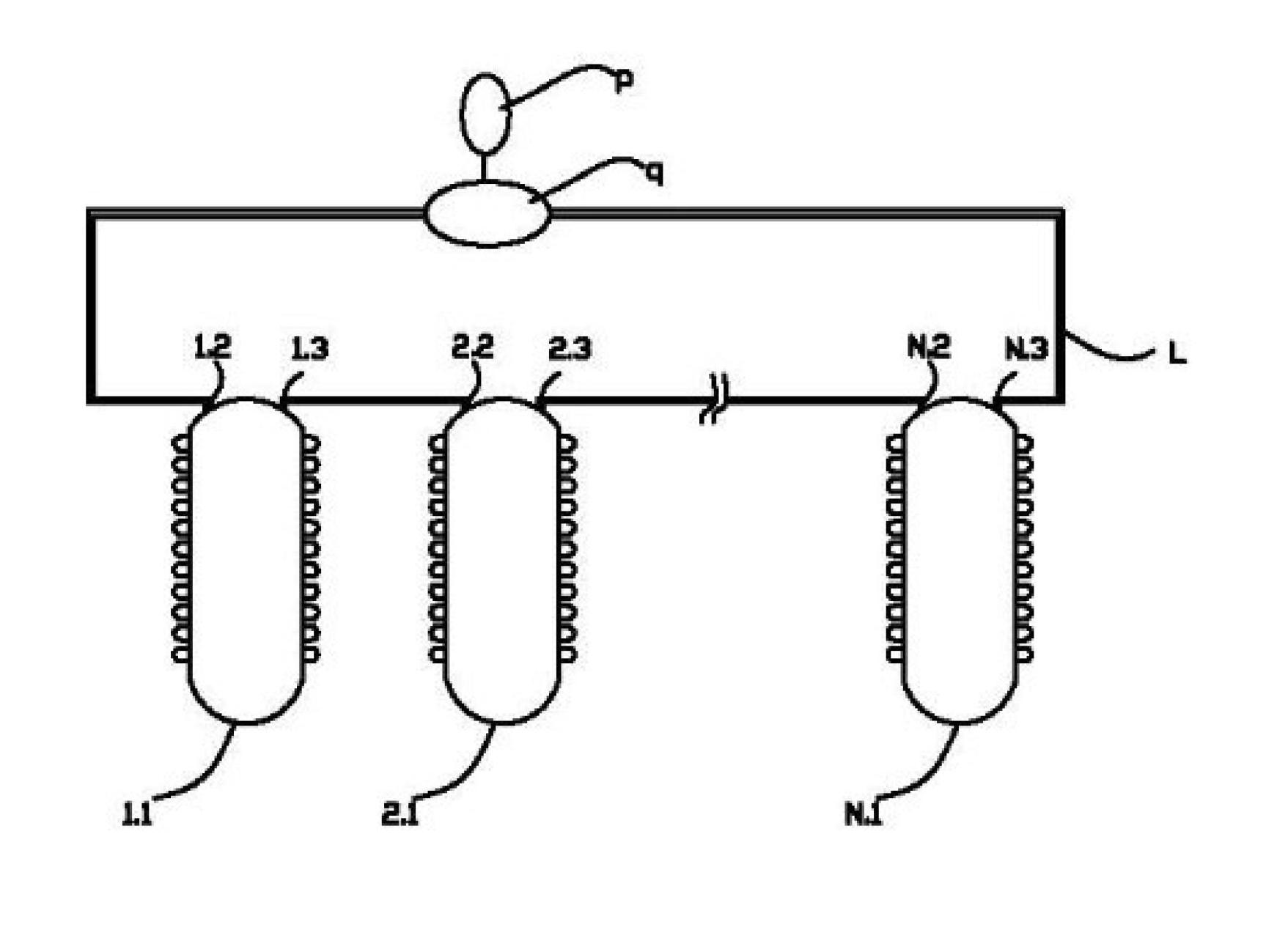
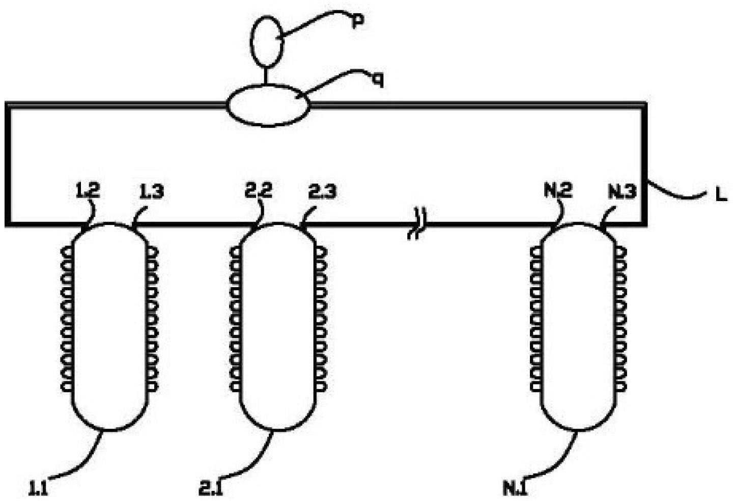
[0018] Such as figure 1 As shown, the LED array heat dissipation system based on liquid circulation includes an LED array composed of N LED bulb lamps (1, 2, ..., N), and the heat dissipation mechanism of each LED lamp (1.1, 2.1, ..., N.1) is set in a cavity shape, and the cavity-shaped heat dissipation mechanism is provided with a liquid inlet end (1.2, 2.2, ..., N.2) and a liquid outlet end (1.3, 2.3, ..., N.3) , the liquid inlet and liquid outlet of two adjacent LED lamps are connected through a liquid pipeline (L), and the liquid inlet and liquid outlet at both ends of the LED array are connected with a liquid circulation drive device (q) through a pipeline, The entire LED array and the liquid circulation driving device drive the liquid in the liquid (q) pipeline to conduct heat, and the liquid circulation driving device (q) is provided with a heat exchange device (not shown in the figure) to export the liquid that has led heat .

[0019] Both the liquid inlet end and th...


PUM


Abstract

The invention discloses a liquid-circulation-based LED array cooling system which comprises an LED array composed of a plurality of LEDs. A cooling mechanism of each LED is in a cavity shape. Each cavity shaped cooling mechanism is provided with a liquid inlet end and a liquid outlet end. The liquid inlet ends and the liquid outlet ends of each two adjacent LEDs are connected through liquid pipelines. The liquid inlet end and the liquid outlet end at two ends of the LED array are connected with a liquid circulation drive device through pipelines. Heat is transferred between the whole LED array and liquid inside a drive liquid pipeline of the liquid circulation drive device. The liquid circulation drive device is provided with a heat exchanger used to guide out liquid carrying LED heat. The manner of liquid circulation cooling is adopted, the LED array composed of the LED lamps is serially connected with the pipelines which are used to circulate for cooling, and accordingly cooling cost for each LED is reduced, and the circulating liquid is capable of transferring heat quickly.

Description

technical field [0001] The invention belongs to the LED heat dissipation technology, and in particular relates to an LED array heat dissipation system which utilizes liquid circulation to derive heat from LEDs. The system realizes uniform heat dissipation for the LED array composed of a plurality of LEDs. Background technique [0002] The invention belongs to the LED heat dissipation technology, and in particular relates to an LED array heat dissipation system which utilizes liquid circulation to derive heat from LEDs. The system realizes uniform heat dissipation for the LED array composed of a plurality of LEDs. [0003] As a new energy-saving lighting source in the 21st century, LED lights have higher luminous efficiency, longer life, low radiation, small size, fast start-up speed, and environmental protection compared with traditional light sources. They have been widely used in life and industry. It has been widely used in production. There are many types of LED lamps, ...

Claims


Application Information

Patent Timeline
Patent Type & Authority Applications(China)
IPC IPC(8): F21V29/02F21Y101/02F21V29/58F21V29/89F21Y115/10
Inventor 孙雪刚
Owner HUIZHOU YOUTECH OPTOELECTRONICS TECH
Why Eureka
Try Eureka