Heat spreader

A technology of vapor chamber and heat absorbing plate, which is applied in lighting and heating equipment, modification by liquid cooling, cooling/ventilation/heating transformation, etc. It can solve problems affecting the heat conduction efficiency of the chamber and restricting the flow space of the working medium, etc. , to achieve the effect of improving heat conduction efficiency, reducing resistance, and uniform heat distribution

Inactive Publication Date: 2012-09-26
FU ZHUN PRECISION IND SHENZHEN +1
View PDF0 Cites 21 Cited by
  • Summary
  • Abstract
  • Description
  • Claims
  • Application Information

AI Technical Summary

Problems solved by technology

Since the grooves are not connected to each other, the working medium in the airtight chamber can only flow along the grooves, which limits the flow space of the working medium and greatly affects the heat conduction efficiency of the chamber

Method used


Image

  • Heat spreader
  • Heat spreader
  • Heat spreader

Examples


Embodiment Construction

[0015] The present invention will be further described below with reference to the accompanying drawings and embodiments.

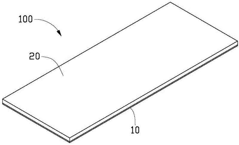
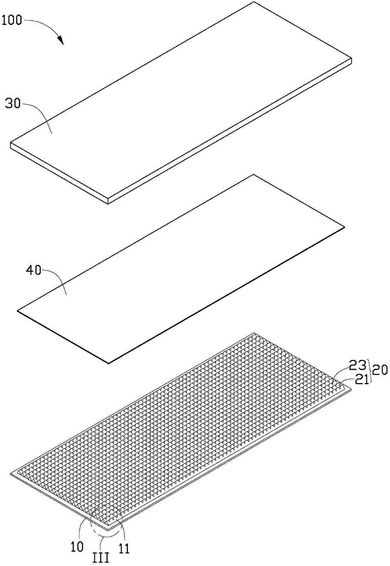
[0016] Such as figure 1 and figure 2 As shown, it is the vapor chamber 100 of the first embodiment of the present invention, which includes a heat absorbing plate 10, a first capillary structure 20 arranged on the heat absorbing plate 10, and a cover set on the heat absorbing plate 10. The heat dissipation plate 30 and the second capillary structure 40 disposed on the lower surface of the heat dissipation plate 30 . The heat radiation plate 30 is disposed on the heat absorption plate 10 and forms a closed chamber with the heat absorption plate 10 . The chamber is evacuated to a low pressure and filled with working media capable of phase change such as water, ethanol, paraffin and the like.

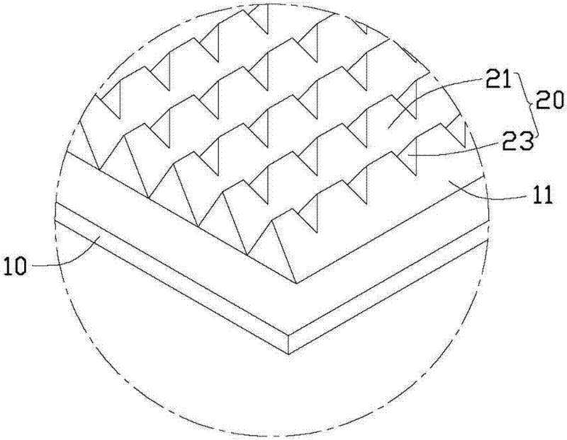
[0017] Please also see image 3 , the heat absorbing plate 10 is made of copper, aluminum or other materials with high thermal conductivity. The lower surface o...


PUM


Abstract

A heat spreader comprises an absorber plate, a heat releasing plate combined with the absorber plate, a first capillary structure on the absorber plate and a second capillary structure on the heat releasing plate, wherein a chamber is formed between the absorber plate and the heat releasing plate; the chamber is filled with a working fluid, and the first capillary structure and the second capillary structure are disposed in the chamber; the first capillary structure comprises several first grooves and second grooves which are arranged parallelly; each of the first grooves extends from one end of the absorber plate to the other end along a vertical direction; each of the first grooves and each of the second grooves are interlaced. Therefore, a gaseous working medium is enabled to simultaneously flow in the first grooves and the second grooves, the flowing space for the gaseous working medium and the contact area thereof with a cover plate are increased, and the heat conduction efficiency is improved due to the reduction of heat transfer resistance and reflux resistance.

Description

technical field [0001] The invention relates to a uniform temperature plate, in particular to a uniform temperature plate for dissipating heat from electronic components. Background technique [0002] Electronic components usually generate a large amount of heat during operation. In order to ensure the normal operation of the electronic components, the heat needs to be dissipated in time. The electronic components are usually equipped with a heat sink to dissipate heat. Traditional heat sinks are in contact with electronic components to achieve the purpose of heat dissipation. In order to adapt to higher heat flux, a heat spreader with good thermal conductivity is usually installed between the electronic component and the heat sink. The function of the temperature chamber is to evenly distribute the heat generated by the heating electronic components first, and then transfer it to the radiator, so as to give full play to the efficiency of the radiator. [0003] The existin...

Claims


Application Information

Patent Timeline
Patent Type & Authority Applications(China)
IPC IPC(8): H01L23/427H05K7/20F28D15/04
CPCH01L2924/0002H01L23/427F28D15/046F28D15/0233H05K7/20309Y10T29/49353H01L2924/00
Inventor 严清平王德玉胡江俊
Owner FU ZHUN PRECISION IND SHENZHEN
Why Eureka
Try Eureka