Double-mould turnover casting machine for casting piston
A technology for casting pistons and casting machines, which is used in casting equipment, equipment for transporting casting molds, and manufacturing tools. reasonable effect
- Summary
- Abstract
- Description
- Claims
- Application Information
AI Technical Summary
Problems solved by technology
Method used
Image

Examples
Embodiment Construction
[0018] The present invention will be described in further detail below in conjunction with the accompanying drawings and specific embodiments.
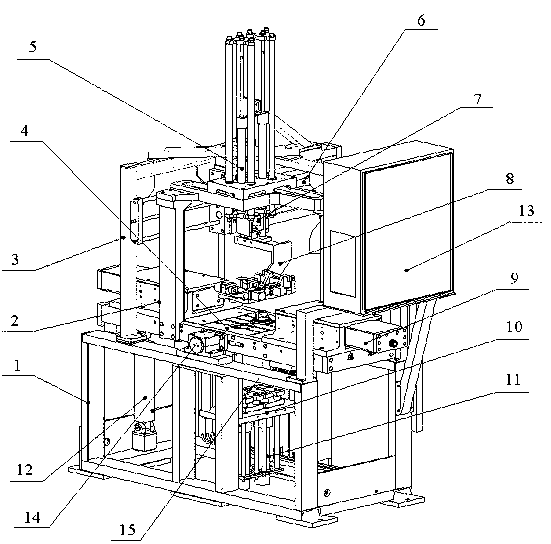
[0019] A double-mold overturn casting machine for casting pistons, the structure of which is as follows figure 1 shown. A frame 1 is included, a workbench and a manipulator are arranged on the frame, and an outer mold mechanism, a center core mechanism and a top mold mechanism are arranged on the workbench.
[0020] The workbench 4 is a rectangular plate structure, and the center of the workbench is provided with a through hole for placing the mould. The workbench is movably arranged on the center support 15 of the frame through the rotating shafts 14 positioned at the both sides of the through hole, and an overturning oil cylinder 12 is arranged under one end of the workbench, and the piston rod of the overturning oil cylinder is connected with the bottom surface of the workbench for use The workbench rotates around the shaft under...
PUM
 Abstract
Description
Claims
Application Information