
Pile reinforcing device and method of self-elevating and self-propelling ship
A self-propelled, pile-leg technology, applied to sheet pile walls, water conservancy projects, artificial islands, etc., can solve problems such as poor resistance to horizontal slipping, poor stability against slipping, and increased draft of the ship to improve maneuverability and work efficiency, the effect of improving the ability to resist horizontal slippage
- Summary
- Abstract
- Description
- Claims
- Application Information
AI Technical Summary
Problems solved by technology
Method used
Image

Examples
Embodiment Construction
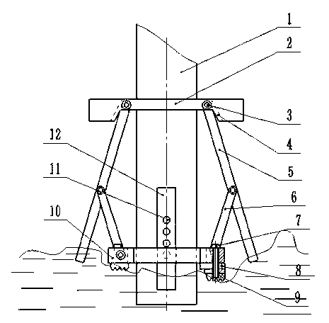
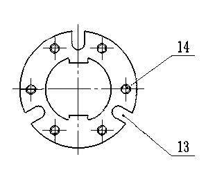
[0012] combine figure 1 and figure 2 It shows a specific embodiment of the pile fixing device of a self-elevating and self-propelled ship of the present invention, which includes a leg 1 and a fixed lug 2, the leg 1 is covered with a fixed lug 2 and a sliding frame 10, and the sliding frame 10 is located at the lower end of the fixed ear plate 2, and the pile legs 1 and the fixed ear plate 2 are fixed by welding. A limit slot 4 corresponding to the rotating pair, and the lower end of the upper connecting rod 5 is connected with the lower connecting rod 6 through the rotating pair, and the other end of the lower connecting rod 6 is connected on the sliding frame 10 through the rotating pair, and on the pile leg 1 Sliding grooves 12 are formed symmetrically at the lower end of the pile at 180°. The sliding frame 10 can slide along the symmetrically distributed sliding grooves 12 outside the legs 1, and a plurality of pin holes 11 are equidistantly arranged in the sliding groov...
PUM
 Abstract
Description
Claims
Application Information