Measuring device for electrical resistivity of electromagnetic waves while drilling and measuring method thereof

A measuring method and technology of measuring device, which can be applied in electromagnetic wave detection, electrical/magnetic detection for logging records, earthwork drilling, etc. problem, to achieve the effect of simple hardware circuit, fewer analog devices, and improved accuracy

Active Publication Date: 2012-10-03
BC P INC CHINA NAT PETROLEUM CORP +1
View PDF8 Cites 51 Cited by
  • Summary
  • Abstract
  • Description
  • Claims
  • Application Information

AI Technical Summary

Problems solved by technology

However, the disadvantage of this method is that the sampling frequency cannot be reduced, and the required formation parameters can be measured at a low sampling frequency
[0005] In the above-mentioned various existing technologies, the attenuation of the amplitude and the offset of the phase will be generated by the influence of the resistivity when the high-frequency electromagnetic wave passes through the formation. The instrument measures the attenuation ratio of the amplitude of the electromagnetic wave and the phase difference of the electromagnetic wave. For Some technologies use the method of hardware circuit measurement, but due to the internal noise interference of the circuit, the reliability and accuracy of the measurement circuit will be affect

Method used


Image

  • Measuring device for electrical resistivity of electromagnetic waves while drilling and measuring method thereof
  • Measuring device for electrical resistivity of electromagnetic waves while drilling and measuring method thereof
  • Measuring device for electrical resistivity of electromagnetic waves while drilling and measuring method thereof

Examples


Embodiment Construction

[0021] The following will clearly and completely describe the technical solutions in the embodiments of the present invention with reference to the accompanying drawings in the embodiments of the present invention. Obviously, the described embodiments are only some, not all, embodiments of the present invention. Based on the embodiments of the present invention, all other embodiments obtained by persons of ordinary skill in the art without making creative efforts belong to the protection scope of the present invention.

[0022] Since the present invention uses the under-sampling technology to sample the high-frequency electromagnetic wave signal, a responsive algorithm is needed to eliminate the frequency-domain aliasing of the under-sampling. The principle is as follows:

[0023] The sampling rate of the traditional electromagnetic wave signal sampling using the Nyquist sampling theorem needs to be higher than the frequency of the sampled electromagnetic wave signal, that is,...


PUM


Abstract

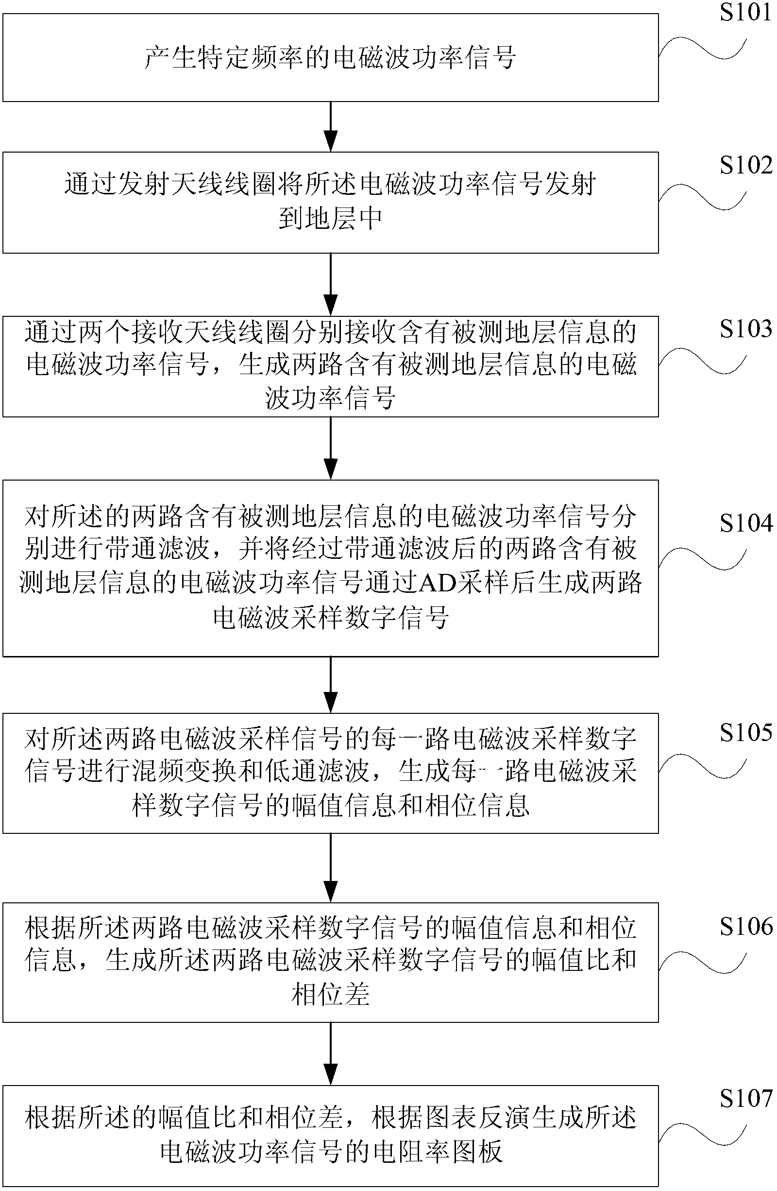
The invention discloses a measuring method for electrical resistivity of electromagnetic waves while drilling, comprising the following steps: generating an electromagnetic wave power signal with specific frequency; emitting the electromagnetic wave power signal into a ground layer through an emitting antenna coil; receiving two electromagnetic wave power signals including measured ground layer information through two receiving antenna coils so as to generate two paths of electromagnetic wave power signals including the measured ground layer information; carrying out band-pass filtering to the two paths of the electromagnetic wave power signals including the measured ground layer information, and carrying out AD sampling to the two paths of the electromagnetic wave power signals including the measured ground information which is subjected to the band-pass filtering so as to generate two paths of electromagnetic sampling digital signals; carrying out frequency mixing transformation and low-pass filtering to the electromagnetic wave sampling digital signals so as to generate amplitude value information and phase information; generating amplitude value ratio and phase difference according to the amplitude value information and the phase information; and generating an electrical resistivity drawing board of the electromagnetic wave power sinals in a chart inversion method according to the amplitude value ratio and the phase difference. An embodiment of the invention also discloses a measuring device for the electrical resistivity of the electromagnetic waves while drilling.

Description

technical field [0001] The invention relates to the field of measurement-while-drilling or logging-while-drilling in oil and natural gas drilling operations, in particular to a method and device for measuring the resistivity of electromagnetic waves while drilling based on a high-frequency under-sampling algorithm used in a geosteering drilling system. Background technique [0002] Electromagnetic wave resistivity is an important geological parameter used in geosteering drilling system for real-time formation evaluation and drilling steering information. The electromagnetic wave resistivity measurement while drilling technology is developed on the basis of the traditional cable electromagnetic wave resistivity measurement technology. It is a measurement method that can measure the formation resistivity in different azimuths around the borehole in real time during the drilling process. Logging while drilling is an advanced logging technology that has developed rapidly in rece...

Claims


Application Information

Patent Timeline
IPC IPC(8): E21B49/00E21B47/13G01V3/30
Inventor 贾衡天张程光艾维平宋延淳邓乐
Owner BC P INC CHINA NAT PETROLEUM CORP
Why Eureka
Try Eureka