
Pneumatic pumping energy storage system and potential energy generation system

A hydraulic generator and air pressure technology, applied in the field of energy storage, can solve the problems of affecting power generation, power consumption, long time, etc., and achieve the effect of improving water lifting efficiency, improving work efficiency, and high-efficiency water pumping

Active Publication Date: 2012-10-03
NANTONG REASON ENVIRONMENTAL PROTECTION TECH CO LTD
View PDF10 Cites 8 Cited by
  • Summary
  • Abstract
  • Description
  • Claims
  • Application Information

AI Technical Summary

Problems solved by technology

[0006] (1) The above-mentioned patent realizes the improvement of the water storage potential energy through the principle of leverage, which belongs to intermittent water lifting, and the amount of water lifted each time is limited to a certain extent, the efficiency of water lifting is low, and it takes a long time to reach a certain amount of power generation the water lifting process;
[0007] (2) Due to the use of the principle of leverage to lift water, the height of the water is also limited to a certain extent, and it is impossible to lift the water to a higher place. Therefore, the potential energy of the water after water lifting is small. According to the law of energy, This will inevitably affect the power generation after conversion
[0008] (3) The process of lever lifting water consumes a certain amount of electric energy
[0011] (1) The water supply method of the air pressure water pump in the above-mentioned patent documents is that the exhaust gas of the first water pump enters the second water pump, and the second water pump enters the third, so that the water raised by the multiple water pumps Used at different heights, its structure is complex, and each water pump is intermittently pumping water, that is, it does not drain water when exhausting, so its drainage efficiency is low

Method used


Image

  • Pneumatic pumping energy storage system and potential energy generation system
  • Pneumatic pumping energy storage system and potential energy generation system
  • Pneumatic pumping energy storage system and potential energy generation system

Examples


Embodiment Construction

[0093] In order to make the object, technical solution and advantages of the present invention clearer, the implementation manner of the present invention will be further described in detail below in conjunction with the accompanying drawings.

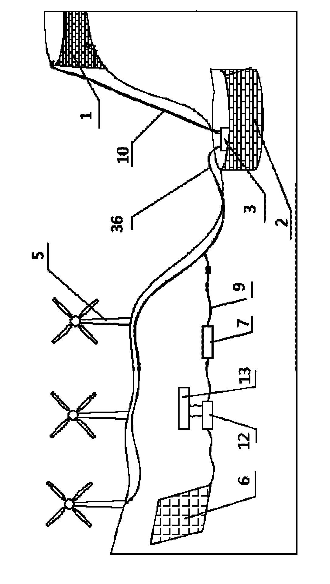
[0094] figure 1 Shown is a pneumatic water pumping energy storage system, including a low-level water storage tank 2, a high-level water storage tank 1, an energy supply device and a water lifting device. The water in the pool 2 is carried to the high-level water storage tank 1, and the water lifting device here is an air pump 3, and the energy supply device is connected with the air intake pipe 36 of the air pump 3 through an air circuit.

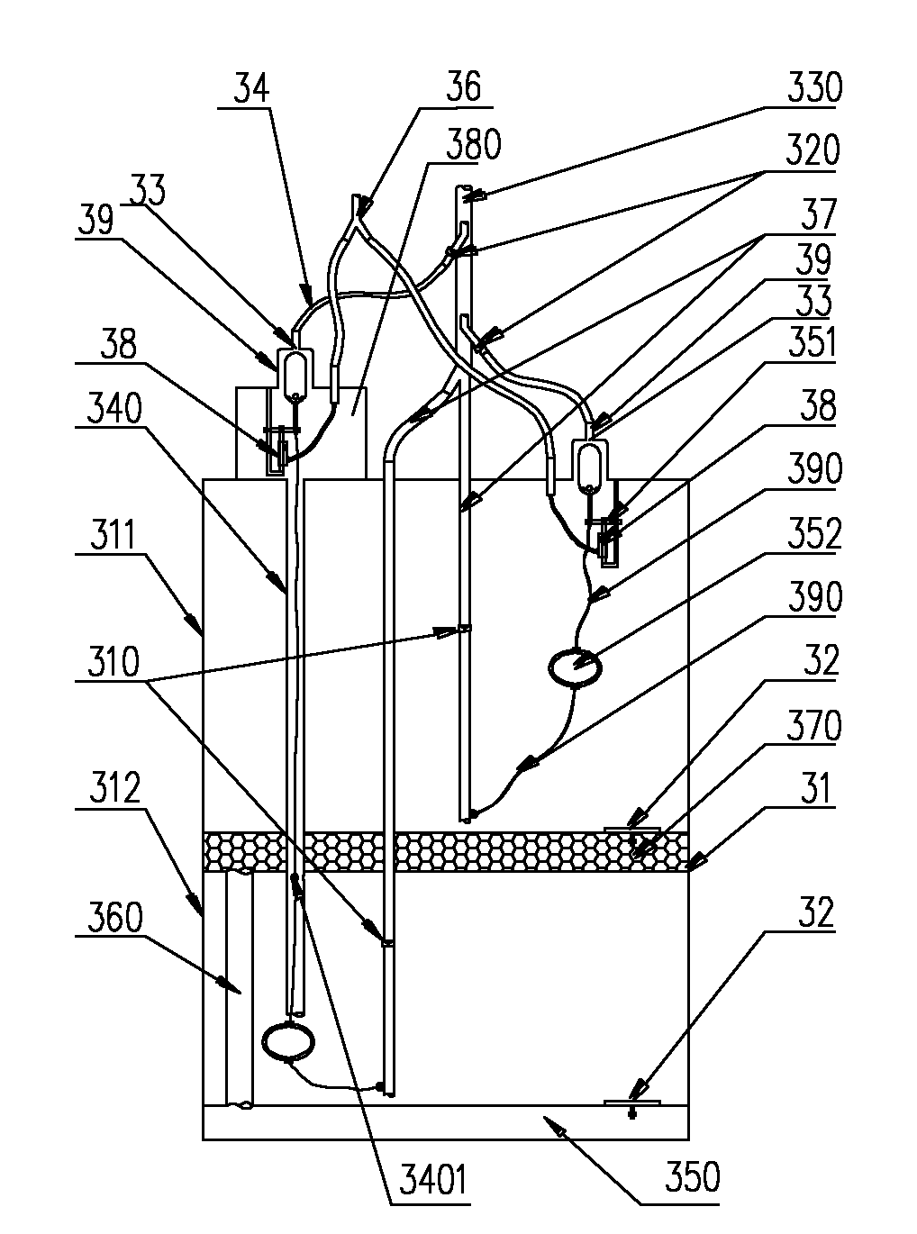
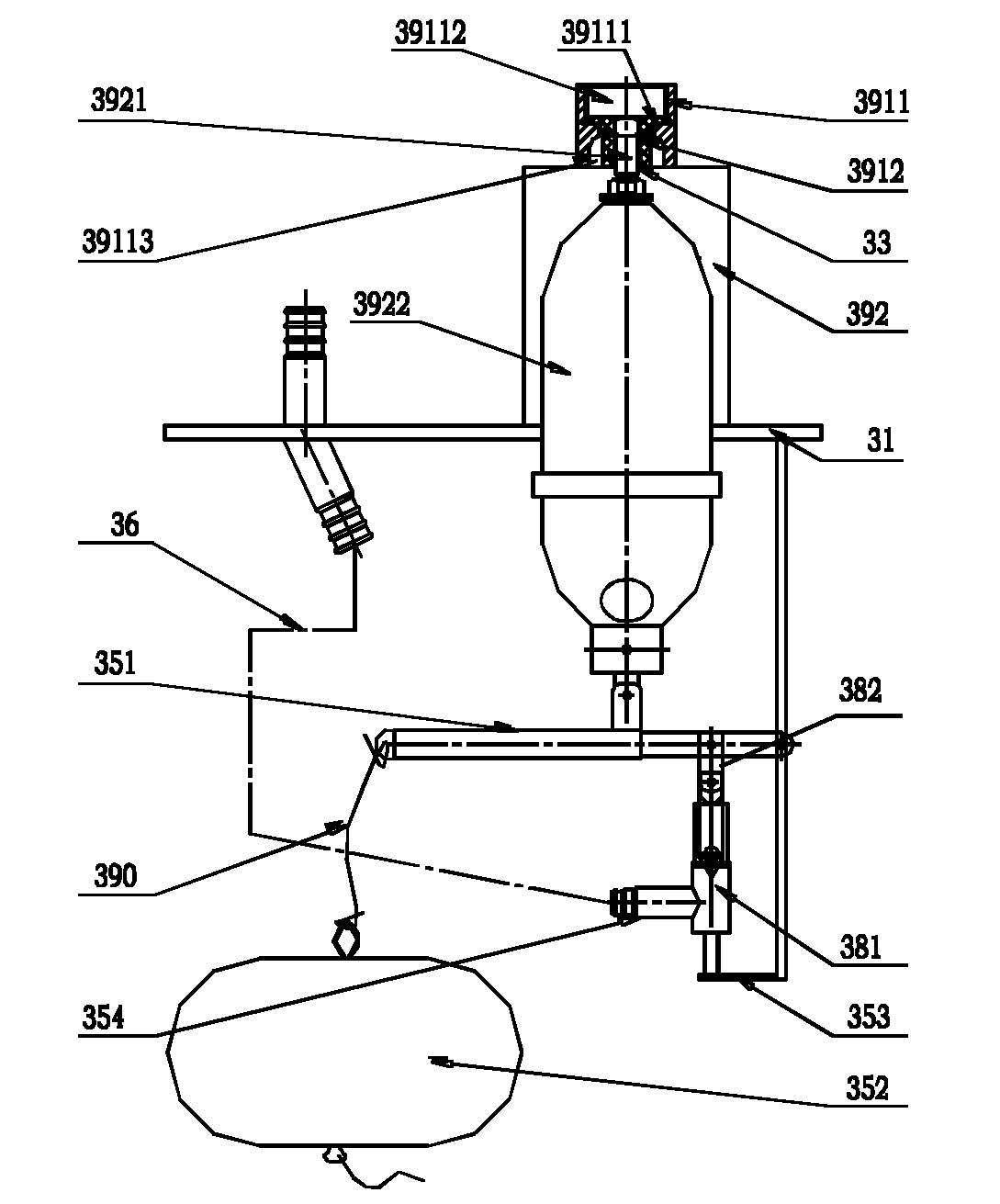
[0095] Such as figure 2 As shown, the pneumatic water pump 3 includes:

[0096] The cylinder body 31 is placed in the low-level water storage tank 2, and the interior of the cylinder body 31 is divided into two cylinder bodies 311, 312. The two cylinder bodies 311, 312 are respectively provided ...


PUM


Abstract

The invention discloses a pneumatic pumping energy storage system and a potential energy generation system. The pneumatic pumping energy storage system comprises a low reservoir, a high reservoir, an energy supplying device and a water lifting device. The water lifting device is connected with the energy supplying device and is used for lifting water in the low reservoir to the high reservoir. Pressure gas provided by the energy supplying device is acted in a pneumatic water pump, energy of the pressure gas is converted to potential energy of the water, and accordingly the water is lifted to the reservoir with high potential energy. The potential energy can be converted to electric energy by a hydroelectric generator as needed. By the pneumatic water pump, continuous water lifting is achieved, and energy storage efficiency and water storage energy are improved.

Description

technical field [0001] The invention relates to the field of energy storage, in particular to a pneumatic pumping water energy storage system and a potential energy power generation system. Background technique [0002] The technology of using energy storage has long been known to people. For example, building a dam to store water and then using the head of the water store to generate kinetic energy to drive a generator to generate electricity is an example. However, this method requires the construction of a dam and other equipment, and its cost is huge. The stored water after generating electricity can not be reused unless the discharged water is pumped back to use with other water pumping devices, but more power consumption is required to directly pump back water with this water pumping device. [0003] The current wind power generation or solar power generation technologies all use energy storage equipment to store the generated electric energy. [0004] Chinese patent ...

Claims


Application Information

Patent Timeline
IPC IPC(8): F04F1/06F03D9/00F03B13/06F03D9/17
CPCY02E60/17Y02E10/72Y02E10/22Y02E10/20Y02E60/16Y02E70/30Y02P80/10
Inventor 张延胜
Owner NANTONG REASON ENVIRONMENTAL PROTECTION TECH CO LTD
Learn More