Combined automatic air drying and balancing device for sample preparation
An air drying and balancing device technology, which is applied in the direction of non-progressive dryers, static material dryers, local stirring dryers, etc., can solve the problems of heavy manual labor, easy sample mixing, and manual memory required for drying and balancing time, etc. problems, to achieve the effect of improving drying and balancing efficiency, increasing the degree of automation, and reducing labor intensity
- Summary
- Abstract
- Description
- Claims
- Application Information
AI Technical Summary
Problems solved by technology
Method used
Image

Examples
Embodiment 1
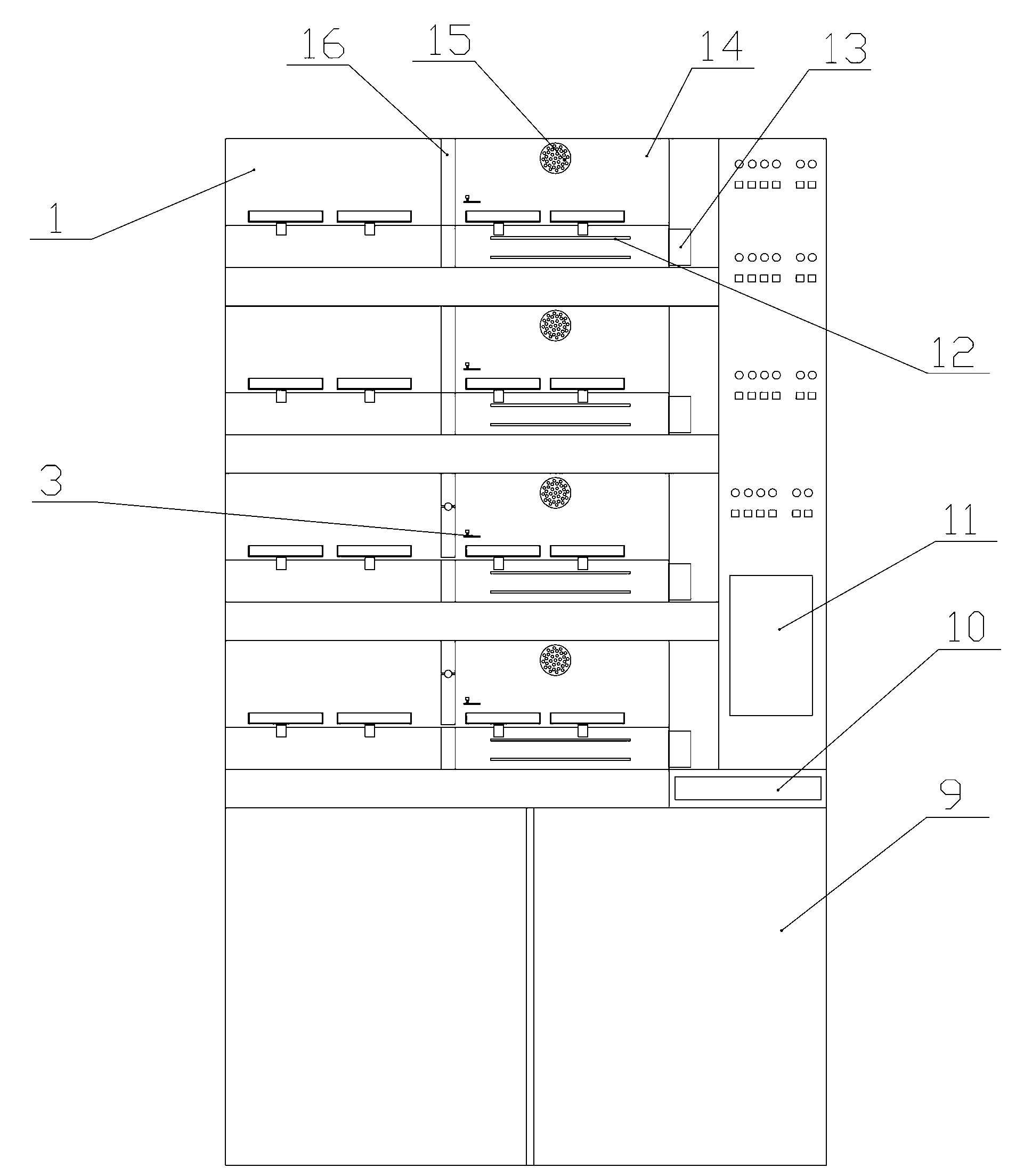
[0027] Embodiment 1: as figure 1 and figure 2 As shown, the combined automatic air drying balance device for sample preparation of the present invention includes more than one drying balance assembly and a control box 7, and each drying balance assembly includes a side-by-side arrangement and is separated by a middle partition 16. The air balance box 1 and the heating and drying box 14; the heating and drying box 14 is relatively closed, and the heating and drying box 14 is provided with a heating sheet 12 and a measurement and control element 3, which has the function of heating / heating constant temperature, and the temperature is controllable; each group of heating and drying boxes 14 all adopt the mode of heating and controlling temperature with independent heating chip 12, and carry out temperature measurement and monitoring with measurement and control element 3. The heating and drying box 14 is provided with an air inlet 13 and an air outlet 15, the air inlet 13 is loc...
Embodiment 2
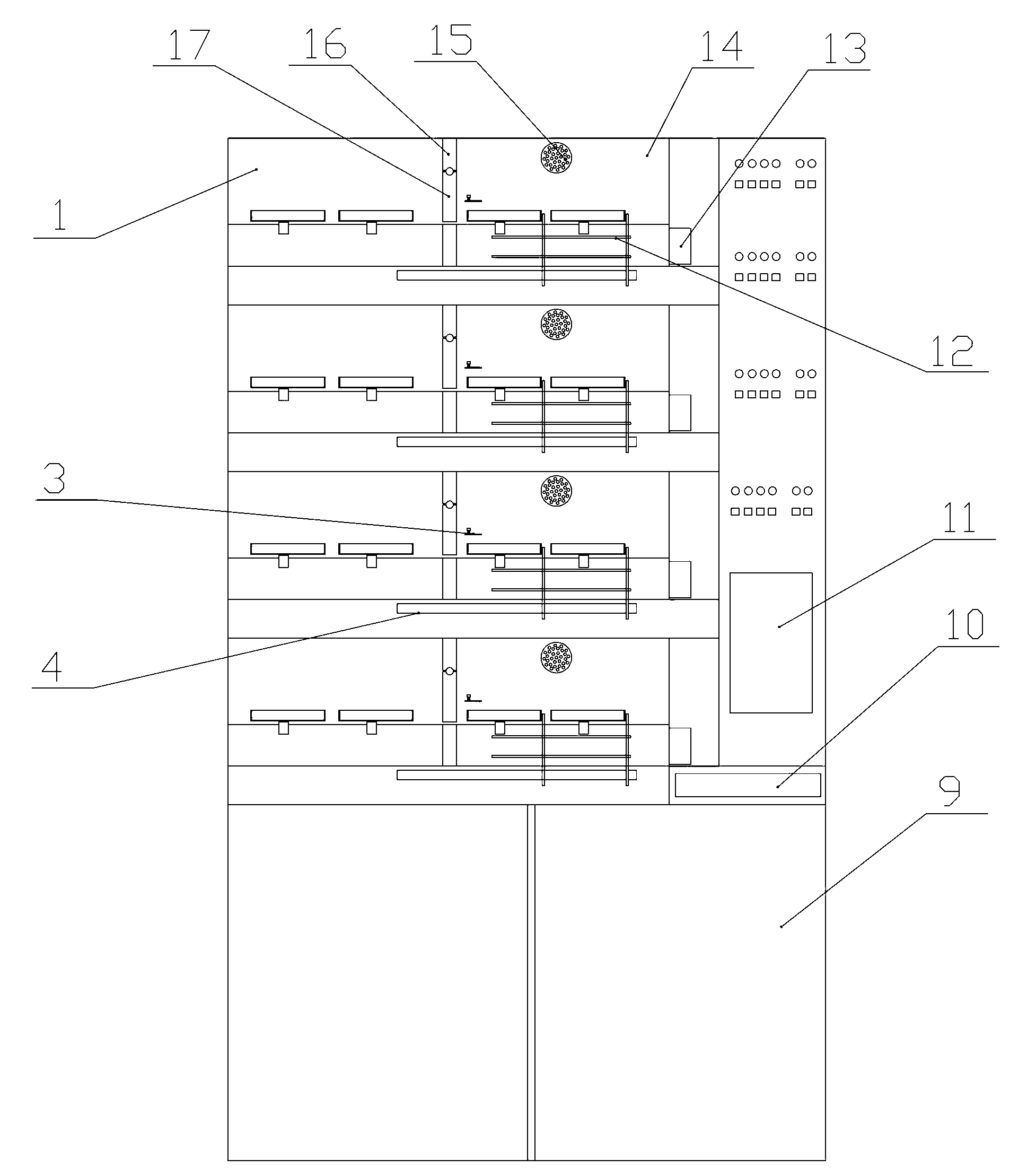
[0032] Embodiment 2: as image 3 and Figure 4 As shown, the structure of this embodiment is basically the same as that of Embodiment 1, the difference is that this embodiment is further used to move the sample tray 6 from the heating drying box 14 to the sample transfer assembly 4 of the air balance box 1 . When the heating and drying time of the sample tray 6 is up, the qualified sample tray 6 can be automatically pushed into the air balance box 1 by the sample transfer component 4 .
[0033] In this embodiment, a movable door 17 is hinged on the middle partition 16. When the sample tray 6 moves under the driving of the sample transfer assembly 4, the sample tray 6 can push the movable door 17 to turn over. After the sample tray 6 passes through, the movable door 17 and reliable dead weight self-closing. It can be understood that the dodge door 17 can also be driven by means or mechanisms such as electric, pneumatic, magnetic and hydraulic, and is controlled by the control...
Embodiment 3
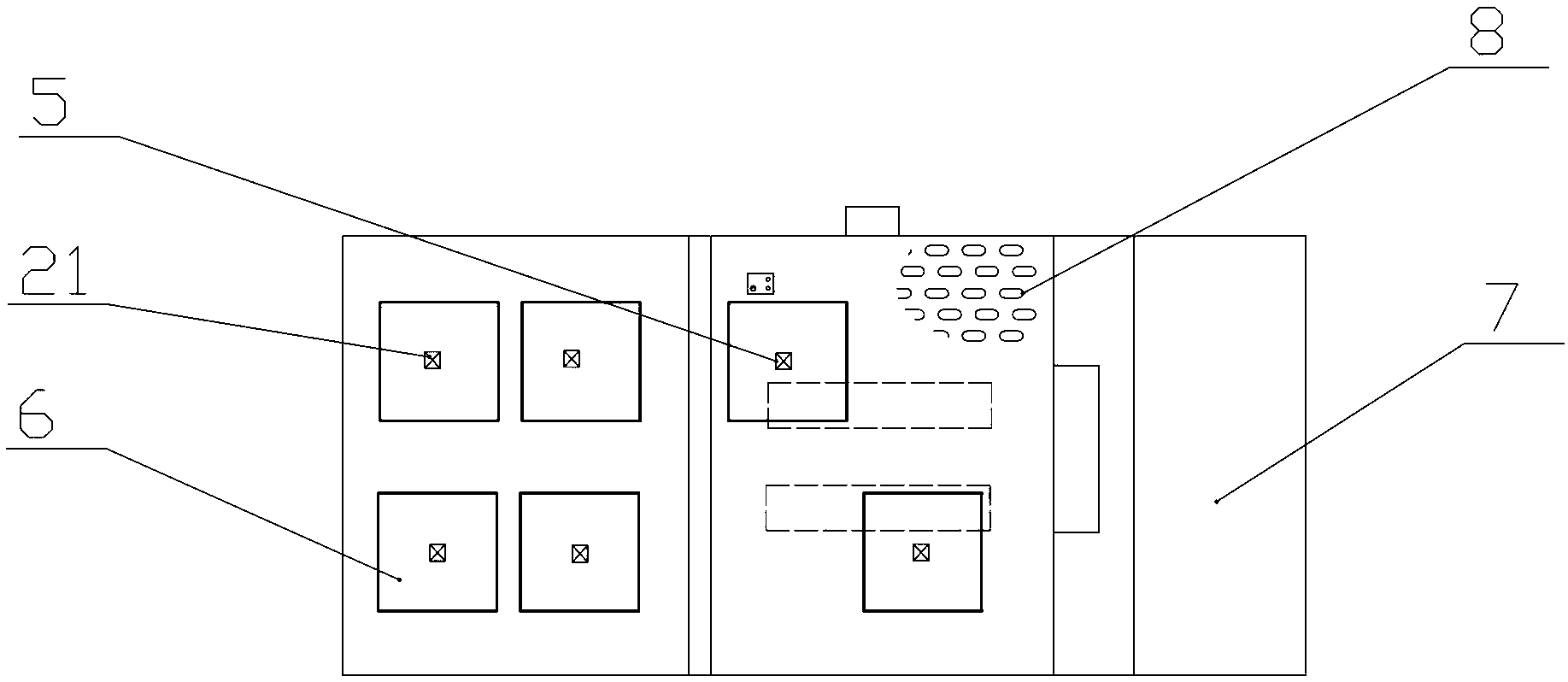
[0036] Embodiment 3: as Figure 5As shown, the structure of this embodiment is basically the same as that of Embodiment 2, and the difference is that: this embodiment is further provided with a dehumidification assembly 2, a first The valve 18 and the second valve 19 form a closed cycle of the gas circuit. After the air flow passes through the air inlet 13, it passes through the heating plate 12 to bring the hot air upward from the air-permeable interlayer 8 into the heating chamber, and the water vapor is brought out from the upper air outlet 15, and the air flow with water flow enters the dehumidification component 2, after removing the moisture The dry air flow flows into the heating drying box 14 from the air inlet 13 again.
[0037] The dehumidification assembly 2 can be equipped with multiple sets of drying balance assemblies, and can be connected to the drying balance assembly in working or non-working state through the control of the first valve 18 and the second valv...
PUM
 Abstract
Description
Claims
Application Information
PatSnap Eureka turns technology decisions into work you can execute. Powered by our Innovation Knowledge Graph, it runs expert workflows across engineering, life sciences, materials and intellectual property. Get your review-ready output in minutes.


