Loading test device and method of asymmetric lateral-force-resisting structure

A loading test device, asymmetrical technology, applied in the direction of measuring device, using repeated force/pulsation force to test material strength, instrument, etc., can solve the problem of unreasonable control of horizontal loading and other problems

Inactive Publication Date: 2012-10-03
BEIJING UNIV OF TECH
View PDF2 Cites 21 Cited by
  • Summary
  • Abstract
  • Description
  • Claims
  • Application Information

AI Technical Summary

Problems solved by technology

For the symmetrical structural specimen whose structural layout is exactly the same with respect to the left and right sides of the horizontal loading point, due to its bilateral symmetry and translational deformation, the method of setting distribution beams at the same horizontal height and single-point loading is Yes, the test method is relatively mature; for asymmetric structures with different structures on both sides, if the above method is used to apply horizontal force, due to the asymmetry of the specimen itself relative to the plane of the left and right sides of the horizontal loading point, it is bound to appear in the test. It is difficult to control the torsional deformation, so the horizontal loading cannot be reasonably controlled, so that the test that simulates the actual force situation cannot be carried out

Method used


Image

  • Loading test device and method of asymmetric lateral-force-resisting structure
  • Loading test device and method of asymmetric lateral-force-resisting structure
  • Loading test device and method of asymmetric lateral-force-resisting structure

Examples


Embodiment 1

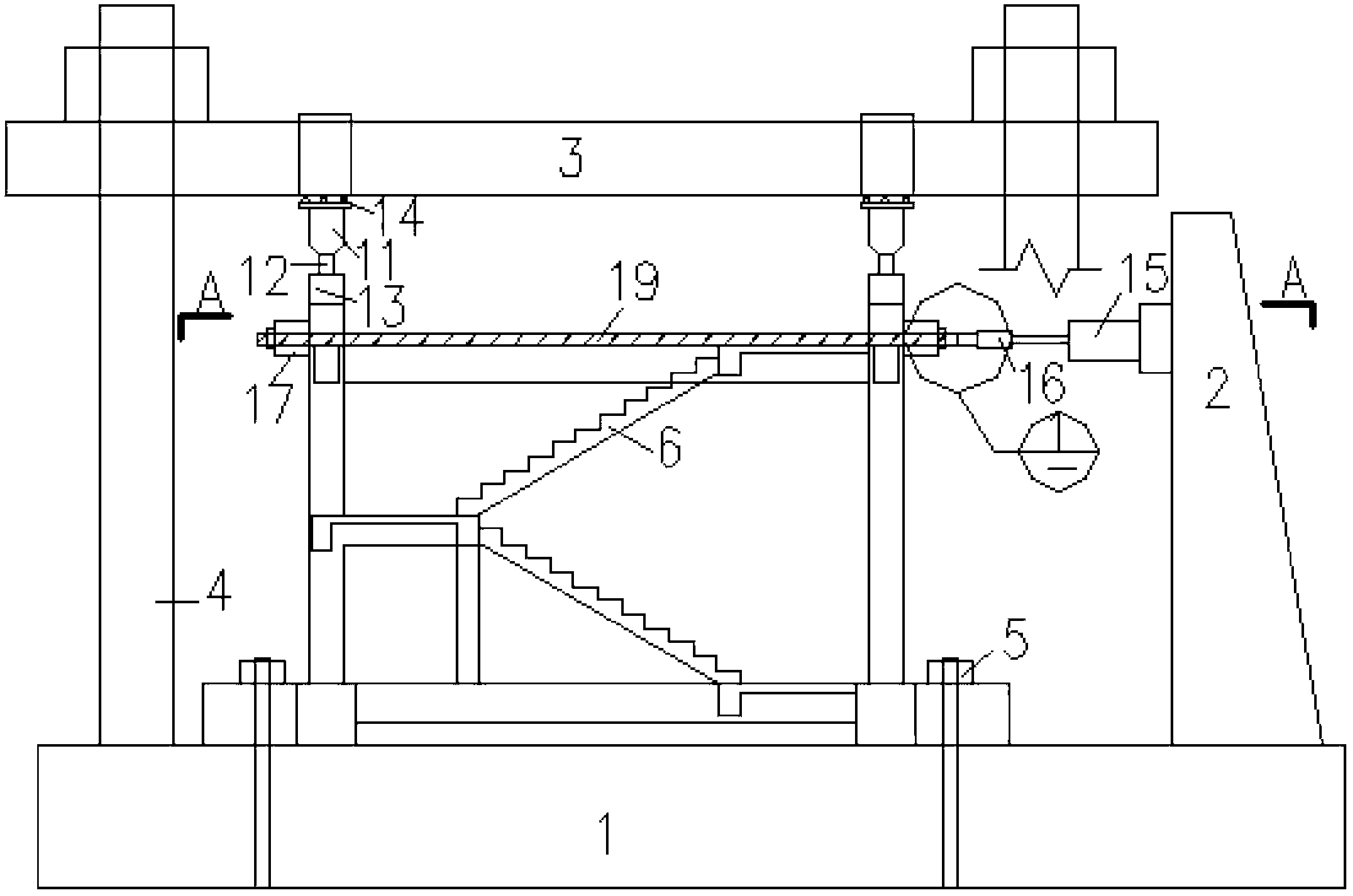
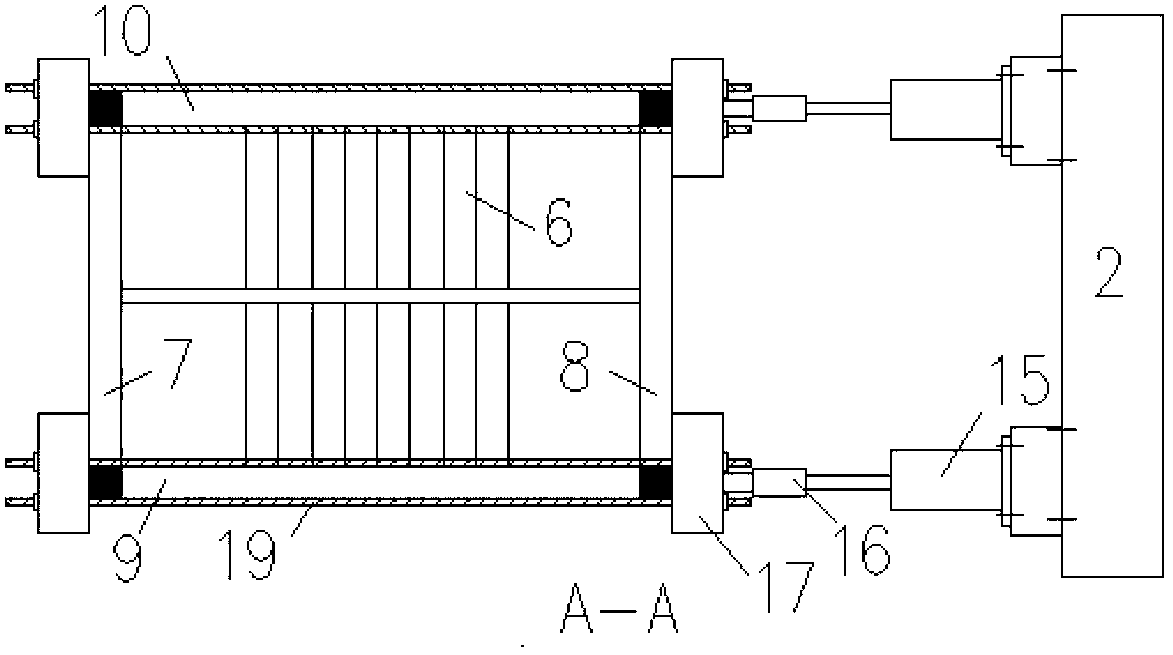
[0026] The structure to be tested in this embodiment is the stairwell substructure test piece 6 .

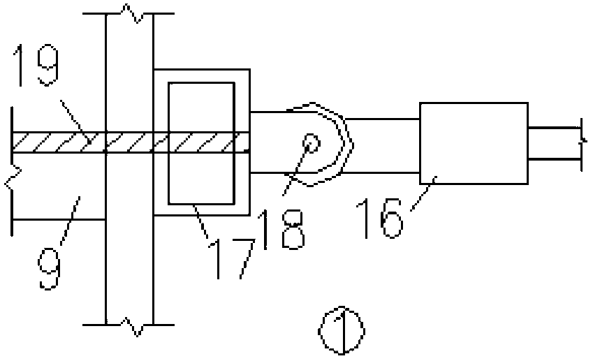
[0027] When it is used as a quasi-static test of the reinforced concrete frame stairwell substructure under the reciprocating action of horizontal force, the loading device is as follows: figure 1 As shown, it consists of a load-bearing system, a front vertical loading system, a rear vertical loading system, a left horizontal loading system, and a right horizontal loading system. The bearing system is divided into a pedestal 1, a reaction wall 2 on the right side of the pedestal 1, a bracket 4 fixed on the pedestal 1, and a reaction beam 3 fixed on the upper part of the bracket 4. The front end vertical loading system is mainly composed of a vertical force jack 11 , a vertical force sensor 12 , a vertical load distribution beam 13 and a horizontal sliding support 14 . The vertical force jack 11 is arranged above the two column tops of the front frame 7 outside the horizontal lo...

Embodiment 2

[0041] The structure to be tested in this embodiment is a substructure test piece 20 composed of a frame and an infill wall frame.

[0042] When the substructure composed of frame and infill wall frame is subjected to quasi-static test under the reciprocating action of horizontal force, the loading device is as follows: Figure 4 As shown, it consists of a load-bearing system, a front vertical loading system, a rear vertical loading system, a left horizontal loading system, and a right horizontal loading system. The bearing system is divided into a pedestal 1, a reaction wall 2 on the right side of the pedestal 1, a bracket 4 fixed on the pedestal 1, and a reaction beam 3 fixed on the upper part of the bracket 4. The front end vertical loading system is mainly composed of a vertical force jack 11 , a vertical force sensor 12 , a vertical load distribution beam 13 and a horizontal sliding support 14 . The position of the vertical force jack 11 corresponds to the top position o...

Embodiment 3

[0055] The structure to be tested in this embodiment is a concrete frame substructure specimen 22 with a steel support on one side.

[0056] When used as a pseudo-static test of a frame structure with steel supports on one side under the reciprocating action of a horizontal force, the loading device is as follows: Figure 6As shown, it consists of a load-bearing system, a front vertical loading system, a rear vertical loading system, a left horizontal loading system, and a right horizontal loading system. The bearing system is divided into a pedestal 1, a reaction wall 2 on the right side of the pedestal 1, a bracket 4 fixed on the pedestal 1, and a reaction beam 3 fixed on the upper part of the bracket 4. The front end vertical loading system is mainly composed of a vertical force jack 11 , a vertical force sensor 12 , a vertical load distribution beam 13 and a horizontal sliding support 14 . The position of the vertical force jack 11 corresponds to the top position of the f...


PUM


Abstract

The invention relates to a loading test device and method of an asymmetric lateral-force-resisting structure, and belongs to the technical field of building structure tests. The test device comprises a bearing system, vertical loading systems and horizontal loading systems, wherein the bearing system comprises a pedestal, a reaction wall, a bracket and a reaction beam. The vertical loading system comprises a vertical force jack, a vertical force sensor, a loading distribution beam and a horizontal sliding support. The number of the horizontal loading systems arranged at the same horizontal height is two or more than two, and the loading of the horizontal loading systems can be independently controlled; each horizontal loading system comprises a horizontal-force jack, a horizontal-force sensor, a hinge connecting piece and a horizontal-force transferring device; and the horizontal-force transferring device consists of a loading beam and a screw nut. When in test, after the vertical force is applied on the structure sample to be tested, the horizontal force is applied on the sample by utilizing the characteristic that all the horizontal loading systems can control loading independently and implementing displacement control, so that the torsion is effectively controlled. The testing device and method can be used for horizontal loading tests of various asymmetric lateral-force-resisting structures.

Description

technical field [0001] The invention relates to a loading test device and method for an asymmetric lateral force-resistant structure, belonging to the technical field of building structure tests. Background technique [0002] The development and deepening of research work in the field of engineering structures largely depends on experimental means and methods. At present, the scale of structural tests is getting larger and larger, not only the test research of large-scale structural components is increasing, but also due to the needs of research, there are continuous requirements for large-scale tests on the overall structure or sub-structures, so the test methods are improved according to actual conditions. method becomes an urgent need. [0003] In structural seismic tests, horizontal low-cycle repeated loading is often used to simulate the situation of lateral force-resistant structures subjected to earthquakes. For the symmetrical structural specimen whose structural l...

Claims


Application Information

Patent Timeline
Patent Type & Authority Applications(China)
IPC IPC(8): G01N3/02G01N3/32
Inventor 赵均许洋徐金蓓王浩刘扬侯鹏程
Owner BEIJING UNIV OF TECH
Why Eureka
Try Eureka