
Fine-tracking control system for optical communication

A control system and fine tracking technology, applied in the field of optical communication, can solve the problems of difficult real-time adjustment of the coaxiality of the beacon light and the target light, complex systems, etc., to achieve the effect of ensuring the coaxiality and improving the suppression ability

Active Publication Date: 2012-10-03
INST OF OPTICS & ELECTRONICS - CHINESE ACAD OF SCI
View PDF4 Cites 9 Cited by
  • Summary
  • Abstract
  • Description
  • Claims
  • Application Information

AI Technical Summary

Problems solved by technology

The disadvantage of this system is: in the vibration environment, it is difficult to adjust the coaxiality of the beacon light and the target light in real time; secondly, the overcoming of the vibration depends entirely on the closed-loop performance of the tracking mirror
However, the system is complex and requires more inertial sensors to stabilize the reference light source

Method used


Image

  • Fine-tracking control system for optical communication
  • Fine-tracking control system for optical communication
  • Fine-tracking control system for optical communication

Examples


Embodiment Construction

[0017] In order to make the object, technical solution and advantages of the present invention clearer, the present invention will be described in further detail below in conjunction with specific embodiments and with reference to the accompanying drawings.

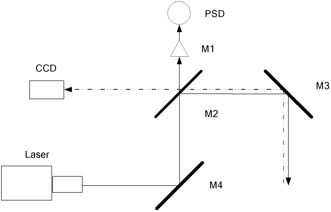
[0018] Such as figure 2 As shown, it is a fine tracking control system for optical communication, which is used to correct the residual error of rough tracking and further improve the tracking and aiming accuracy. It consists of beam expander M1, beam splitter M2, tracking mirror M3, image detector CCD, aiming Composed of mirror M4, position sensor PSD and laser, the tracking mirror M3 receives the target light, and the tracking mirror M3, spectroscopic mirror M2 and image detector CCD are sequentially placed on the beam line of the target light; Sight mirror M4, beam splitter M2, and beam expander M1 are sequentially placed on the beam line; and sight mirror M4, beam splitter M2, and tracking mirror M3 are sequentially ...


PUM


Abstract

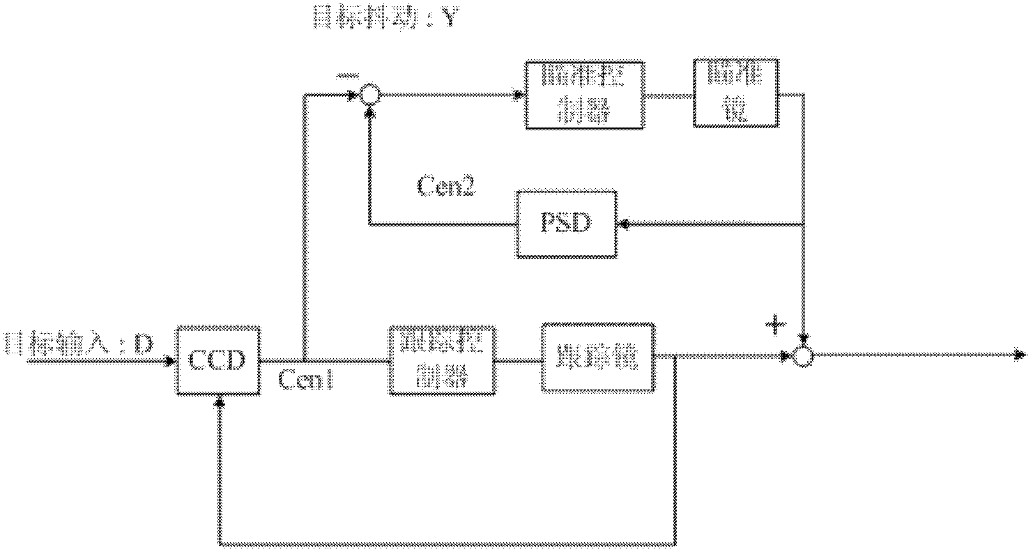
The invention discloses a fine-tracking control system for optical communication. The fine-tracking control system comprises an image detector, a beam expanding mirror, a position sensor, a spectroscope, a tracking mirror, a sighting telescope and a laser. The tracking mirror receives target light; the beam route of a target light is provided with the tracking mirror, the spectroscope and the image detector in order; the laser outputs beacon light and is provided with the sighting telescope, the spectroscope and the tracking mirror on the beam route of the beacon light in order; and the beam route of the beacon light is provided with the sighting telescope, the spectroscope and the tracking mirror in order. The control system provided by the invention is mainly used for high-precision stable control of the optical communication. The system disclosed by the invention utilizes the sighting telescope to correct the difference between the position of the light and the position of the optical axis of the beacon light and enables the difference to be zero in essence. The system provided by the invention is realized as follows: the tracking mirror is in closed loop by utilizing the position of the target light provided by the image detector. The position sensor provides the position of the optical axis and the sighting telescope is in closed loop so as to enable the difference to approach zero.

Description

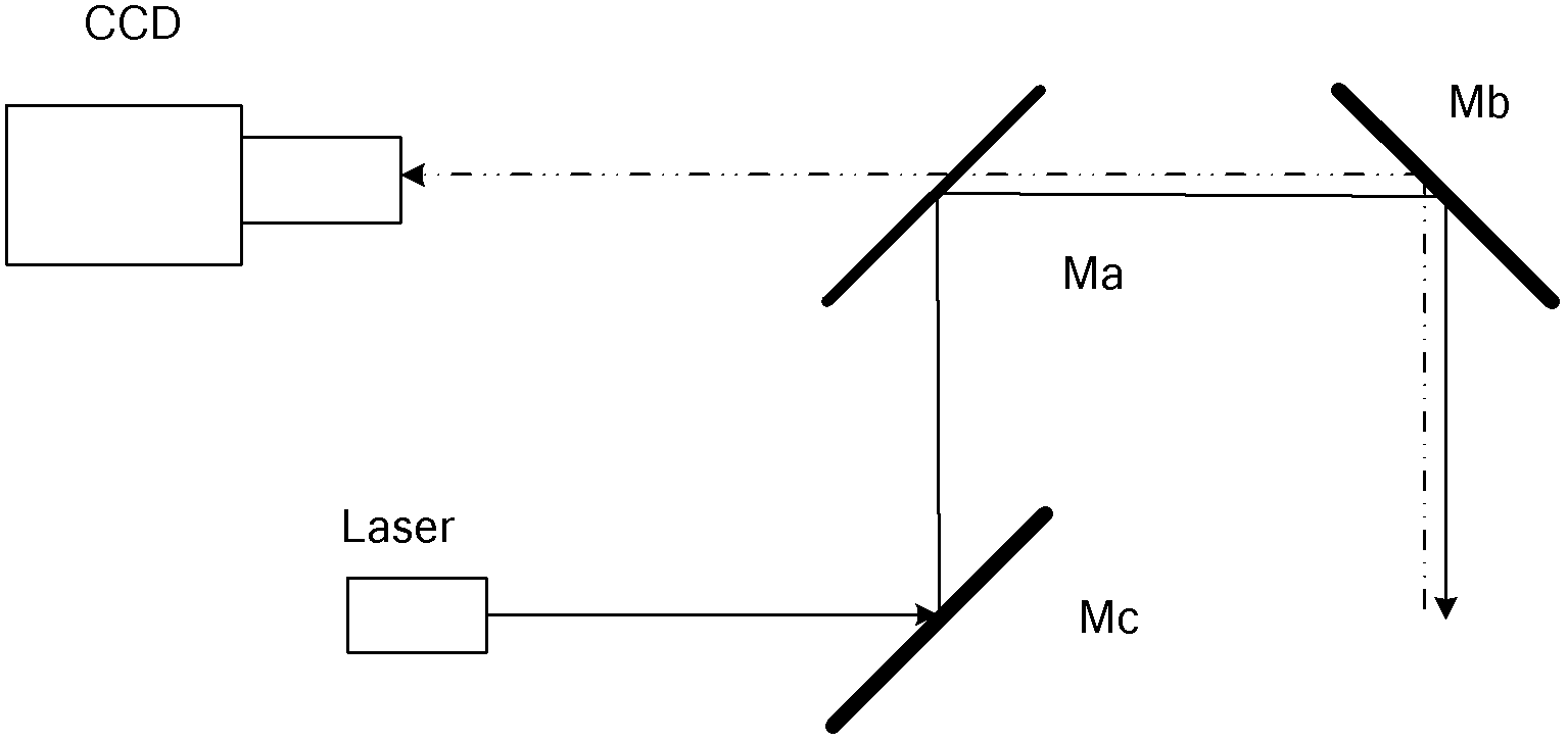
technical field [0001] The invention belongs to the technical field of optical communication, and in particular relates to an optical communication fine tracking control system, which can be used for high-precision tracking and aiming. Background technique [0002] The existing fine tracking control system is shown as figure 1 , including beam splitter Ma, tracking mirror Mb, mirror Mc, and CCD detection system. This method is very simple and has been successfully used in existing fine tracking control systems. The disadvantage of this system is: in the vibration environment, it is difficult to adjust the coaxiality of the beacon light and the target light in real time; secondly, the overcoming of the vibration depends entirely on the closed-loop performance of the tracking mirror. Chinese patent (201110063544.9) introduces an aiming system based on an internal inertial reference light source, which can achieve stable tracking. However, the system is complex and requires ...

Claims


Application Information

Patent Timeline
Patent Type & Authority Applications(China)
IPC IPC(8): G05D3/12G02B23/04
Inventor 唐涛赵华吴琼燕黄永梅包启亮
Owner INST OF OPTICS & ELECTRONICS - CHINESE ACAD OF SCI
Learn More