Shift register unit and gate drive device

A shift register and gate technology, which is applied to instruments, static indicators, etc., can solve the problems of many transistors and high power consumption of shift register units, and achieve the effects of reduced power consumption, less signal wiring, and less occupied area

Active Publication Date: 2012-10-03
BOE TECH GRP CO LTD +1
View PDF5 Cites 17 Cited by
  • Summary
  • Abstract
  • Description
  • Claims
  • Application Information

AI Technical Summary

Problems solved by technology

[0003] from figure 1 It can be seen from the figure that the existing shift register unit needs two latc

Method used


Image

  • Shift register unit and gate drive device
  • Shift register unit and gate drive device
  • Shift register unit and gate drive device

Examples


Embodiment Construction

[0083] The specific implementation manners of the present invention will be further described in detail below in conjunction with the accompanying drawings and embodiments.

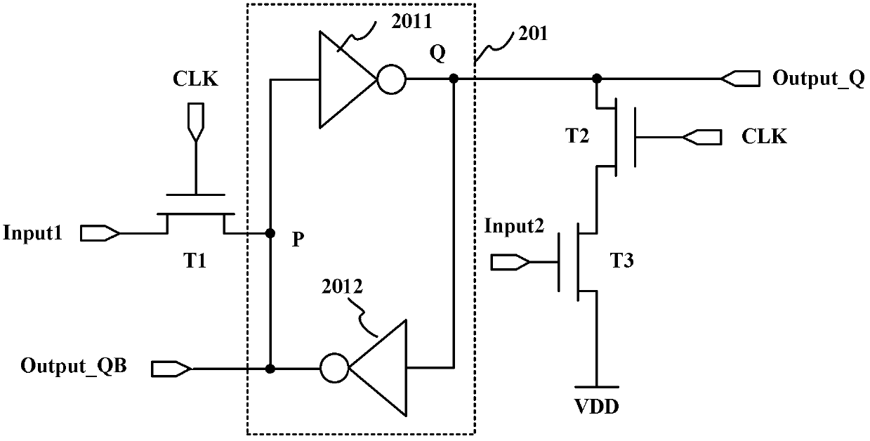
[0084] Such as figure 2 Shown is a schematic structural diagram of a shift register unit according to Embodiment 1 of the present invention, and the shift register unit includes: a latch 201 and a control circuit. For the convenience of description, in the following embodiments, the P node in the figure is used as the input end of the latch 201 , and the Q node is used as the output end of the latch.

[0085] Wherein, the control circuit is used to control the latch 201 to program or latch the output signal, including: a first thin film transistor T1, a second thin film transistor T2 and a third thin film transistor T3. In this embodiment, the first thin film transistor T1, the second thin film transistor T3 Both the second thin film transistor T2 and the third thin film transistor T3 are NMOS transisto...


PUM


Abstract

The invention provides a shift register unit and a gate drive device. The shift register unit comprises a latch and a control circuit, wherein the control circuit comprises a first thin film transistor, a second thin film transistor and a third thin film transistor; the gate of the first thin film transistor is connected with a clock signal input end; the source of the first thin film transistor is connected with a signal input end; the drain of the first thin film transistor is connected with the input end of the latch; the gate of the second thin film transistor is connected with the clock signal input end; the source of the second thin film transistor is connected with a first signal output end; the gate of the third thin film transistor is connected with the signal input end; the source of the third thin film transistor is connected with a high-level signal input end; the drain of the third thin film transistor is connected with the drain of the second thin film transistor; the latch comprises a first phase inverter and a second phase inverter which are connected with each other end to end; the input end of the latch is connected with a second signal output end; the output end of the latch is connected with the first signal output end; and the levels of output signals of the first signal output end and the second signal output end are opposite. According to the shift register unit, the circuit is simple in structure, a small number of signal wires are arranged, the power consumption is low, and the area of a layout is small.

Description

technical field [0001] The present invention relates to the field of display technology, in particular to a shift register unit and a gate driving device. Background technique [0002] The gate driving device of the display is used to provide driving signals for the gate lines, and the gate driving device includes multiple cascaded shift register units, such as figure 1 Shown is a schematic structural diagram of a shift register unit in the prior art, the shift register unit includes: 2 latches 101 and 4 transmission gates 102, wherein one latch 101 is used for programming, and the other latch The register 101 is used to latch the output signal, and the transfer gate 102 is used to control the latch 101 to program or latch the output signal. From figure 1 It can be seen from the figure that each latch 101 is composed of two inverters (the Reset signal input to the Reset (reset) signal input terminal of the NAND gate in the figure is high level, so the NAND gate is also equ...

Claims


Application Information

Patent Timeline
IPC IPC(8): G09G3/20
Inventor 祁小敬谭文
Owner BOE TECH GRP CO LTD
Why Eureka
Try Eureka