Process for preparing cathode grid line of solar cell

A solar cell, front electrode technology, applied in sustainable manufacturing/processing, circuits, electrical components, etc., to improve burn-through capability, enhance ohmic contact, and reduce contact resistance

Active Publication Date: 2012-10-03
SUZHOU ISILVER MATERIALS
View PDF5 Cites 4 Cited by
  • Summary
  • Abstract
  • Description
  • Claims
  • Application Information

AI Technical Summary

Problems solved by technology

Therefore, the current slurry can

Method used


Image

  • Process for preparing cathode grid line of solar cell
  • Process for preparing cathode grid line of solar cell
  • Process for preparing cathode grid line of solar cell

Examples


Embodiment 1-5

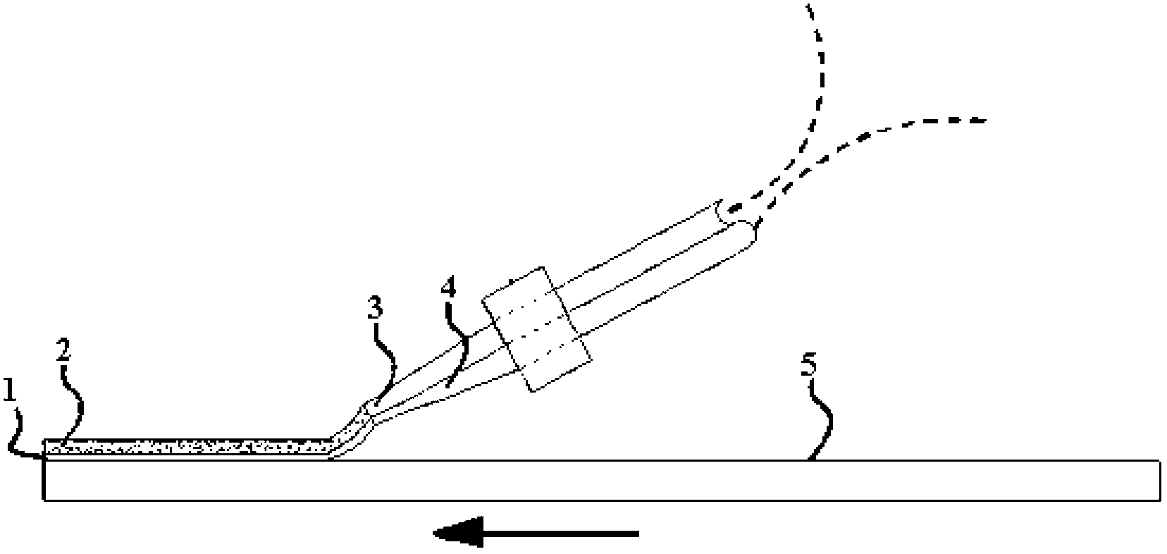
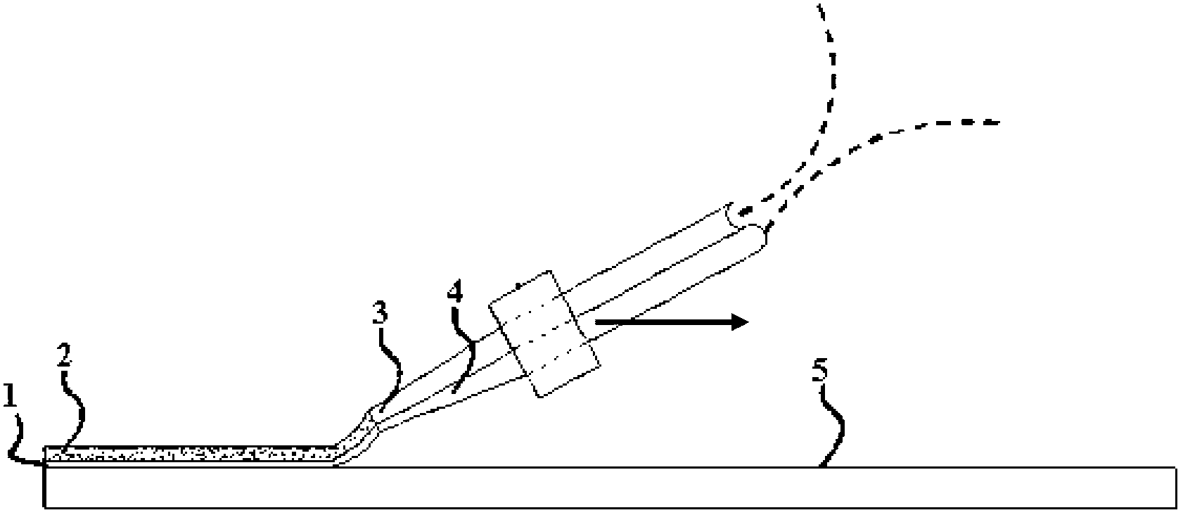
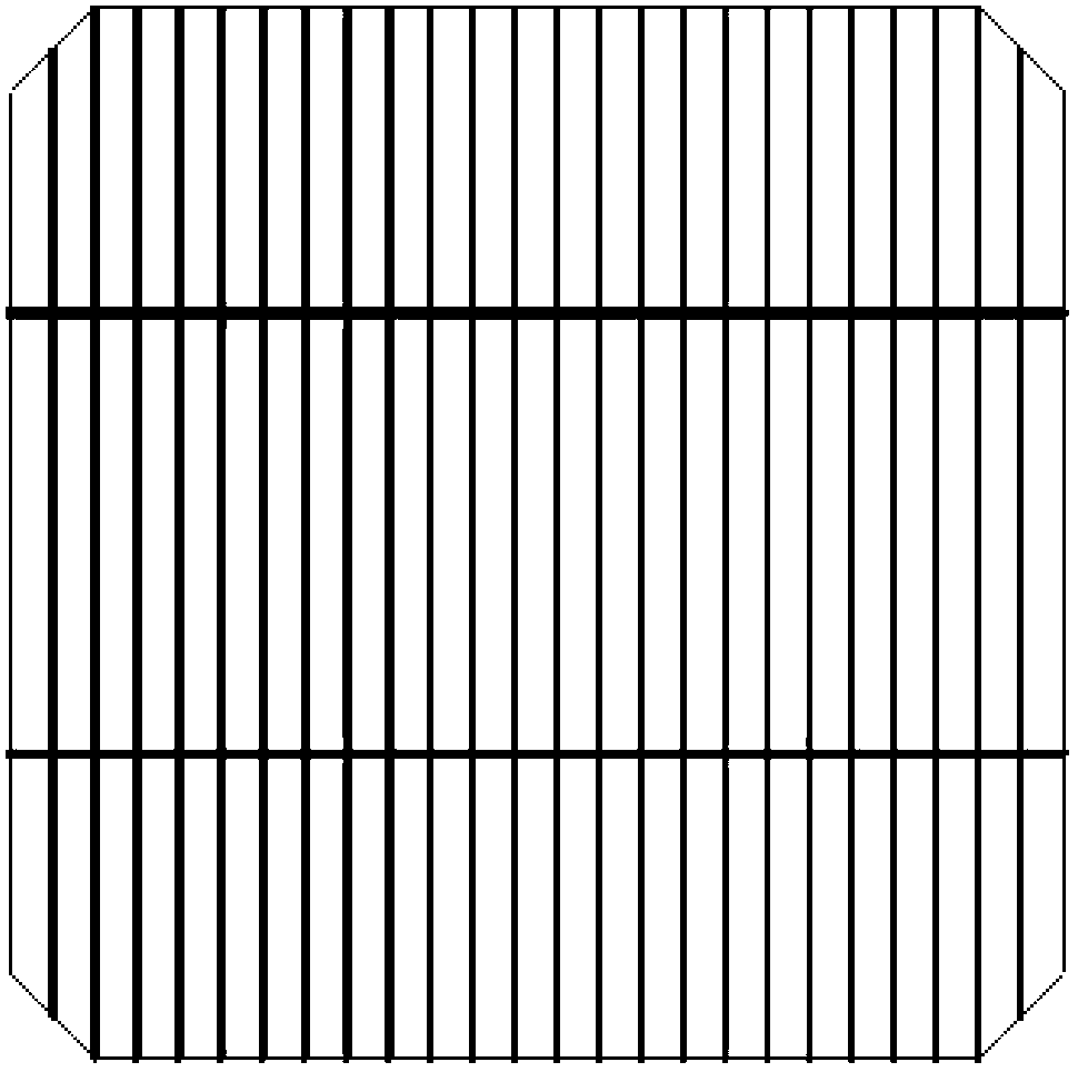
[0036] Embodiment 1-5: A preparation process of solar cell front electrode grid wire, as attached Figure 1-3 As shown, the front electrode grid line of the battery is composed of a first slurry layer 1 and a second slurry layer 2 located on the upper surface of the first slurry layer 1;

[0037] Put the first slurry (A) and the second slurry (B) into containers connected to the lower nozzle 4 and the upper nozzle 3 respectively, the lower nozzle 4 and the upper nozzle are arranged in parallel closely and the upper nozzle 3 Located on the upper side of the lower nozzle 4; the spraying pressure of the lower nozzle 4 is 0.5MPa, the spraying pressure of the upper nozzle 3 is 0.65MPa, and the travel speed of the lower nozzle 4 and the upper nozzle 3 is 125mm / s; the front electrode grid line of the battery 5 is baked Drying temperature 140~160℃, drying time 14~16 minutes;

[0038] The first slurry (A) is composed of the following components in parts by weight:

[0039] Organic ve...


PUM

PropertyMeasurementUnit
Particle sizeaaaaaaaaaa
Widthaaaaaaaaaa
Heightaaaaaaaaaa

Abstract

The invention discloses a process for preparing a cathode grid line of a solar cell. The cathode grid line of the solar cell consists of a first paste layer and a second paste layer positioned on the upper surface of the first paste layer. First paste and second paste are loaded into containers which are connected with a lower nozzle and an upper nozzle respectively. The upper and lower nozzles are tightly attached and arranged in parallel, and the lower nozzle is positioned on the upper lateral surface of the upper nozzle. The spray coating pressure of the lower nozzle is 0.5MPa, and the spray coating pressure of the upper nozzle is 0.65MPa. The travel speed of the lower and upper nozzles is 125mm/s. The first paste consists of an organic carrier, silver powder, glass powder and an ohm contact additive. The second paste consists of an organic carrier, silver powder, glass powder and a metallic-phase adhesive. A high-aspect ratio cathode of the solar cell can be prepared, and a problem about positioning accuracy is solved; and in addition, requirements for a cathode shape and electrical conductivity can be met, and silicon chip fragmentation caused by pressure applied to a silicon chip in a machining process can be avoided.

Description

technical field [0001] The invention relates to a preparation process of a front electrode grid line of a solar cell, and belongs to the technical field of solar cell preparation. Background technique [0002] A solar cell is a semiconductor device with "photovoltaic effect". The PN junction of the device generates voltage after being illuminated, that is, the process of generating electrical energy from light energy. Then, according to the above principle, the most critical thing is that there must be a connected circuit to form electrical energy into a current. to use. Therefore, it is very important to prepare electrodes on the surface of solar cells to draw current. At present, the industrialized solution is to print paste on both sides of the solar cell to make electrodes, one of which is used for the aluminum or aluminum / silver electrode on the back of the solar cell; the other is used for the light-receiving surface (front) of the solar cell Compared with the perfor...

Claims


Application Information

Patent Timeline
IPC IPC(8): H01L31/18H01L31/0224
CPCY02P70/50
Inventor 周欣山汪山傅坚
Owner SUZHOU ISILVER MATERIALS
Why Eureka
Try Eureka