Dynamic idle compensation device for controlling high voltage based on IGBT (Insulated Gate Bipolar Translator)

A compensation device and a dynamic technology, applied in the direction of reactive power compensation, reactive power adjustment/elimination/compensation, etc., can solve the problems of increasing the technical requirements and cost of reactor production, large short-circuit loss, complex structure, etc., and achieve power consumption Low cost, cost saving, impedance continuously adjustable effect

Inactive Publication Date: 2012-10-03
广州同汇盛南站产业发展有限公司
View PDF5 Cites 13 Cited by
  • Summary
  • Abstract
  • Description
  • Claims
  • Application Information

AI Technical Summary

Problems solved by technology

When the conduction angle of the thyristor is less than 90°, the current of the reactor is non-sinusoidal and contains harmonic components, so the fixed capacitor bank must be designed as a filter or equipped with another filter, which has a complex structure and large losses
In the high-voltage system, in order to reduce the voltage limit of the thyristor, the reactor is often used to increase the secondary winding, and the thyristor is used to adjust the short-circuit impedance value to realize the inductive reactance adjustment of the reactor. However, because the transformer works in the magnetic saturation area, the short-circuit loss is large, and the The production technical requirements and cost of the reactor are increased

Method used


Image

  • Dynamic idle compensation device for controlling high voltage based on IGBT (Insulated Gate Bipolar Translator)
  • Dynamic idle compensation device for controlling high voltage based on IGBT (Insulated Gate Bipolar Translator)
  • Dynamic idle compensation device for controlling high voltage based on IGBT (Insulated Gate Bipolar Translator)

Examples


Embodiment Construction

[0019] The specific embodiment of the present invention will be further described below in conjunction with accompanying drawing:

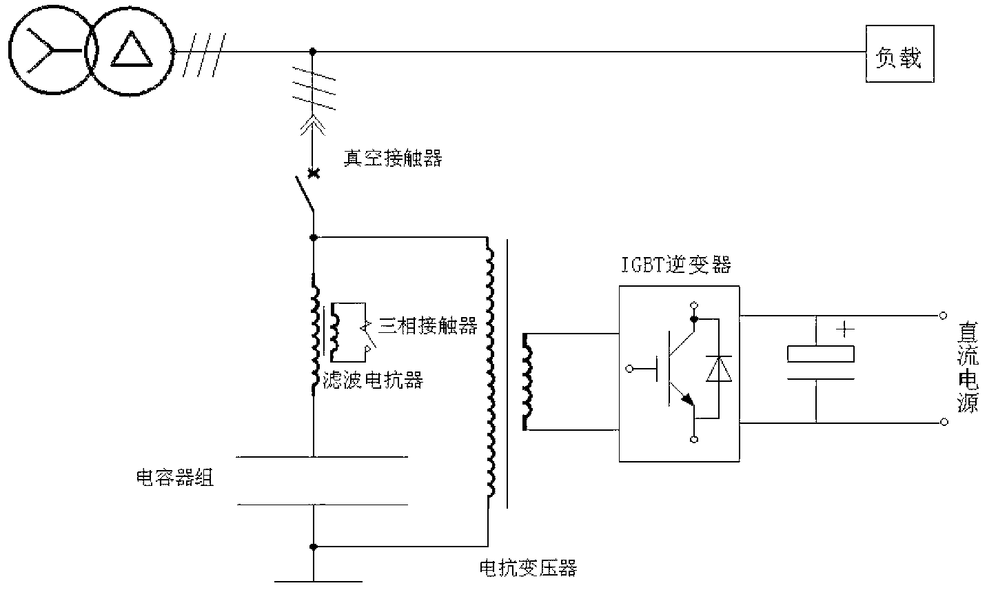
[0020] The dynamic reactive power compensation device of the present invention injects the power frequency current output by the IGBT inverter into the secondary winding side of the reactance transformer, and changes the amplitude of the injected current through the closed-loop control of the power factor to realize the continuous adjustment of the main magnetic flux of the electric control transformer. , to achieve the purpose of adjusting the reactance of the primary winding side of the reactance transformer and realizing reactive power compensation.

[0021] refer to figure 1 , the present invention is based on the IGBT controlled high-voltage dynamic reactive power compensation device, which includes a reactive power compensation branch connected in parallel with the power transmission grid. The reactive power compensation branch includes filt...


PUM


Abstract

The invention discloses a dynamic idle compensation device for controlling high voltage based on an IGBT (Insulated Gate Bipolar Translator), comprising an idle compensation branch which is connected with a power transmission power grid in parallel and further comprising a reactance transformer, wherein the primary winding side of the reactance transformer is connected with two ends of the idle compensation branch in parallel; the secondary winding side of the reactance transformer is connected with a direct-current power supply through an IGBT inverter; and a control end of the IGBT inverter is connected with a control circuit for triggering the control pulse of the IGBT inverter. Alternating-current current is injected into the secondary winding side of the reactance transformer and a main controller is used for comparing a target power factor with a current power factor obtained by calculating collected voltage and current data; a control pulse PWM (Pulse-Width Modulation) waveform for triggering the IGBT inverter is adjusted through closed ring control, so that a current amplitude injected into the secondary winding side of the reactance transformer is changed, the continuous adjustment of a main magnetic flow of an electric transformer is realized, and then the continuous adjustment of the primary winding side of the reactance transformer is realized, and the stepless continuous adjustment of the capacitance and the inductance of the power transmission power grid is realized.

Description

technical field [0001] The invention relates to a dynamic reactive power compensation device, in particular to a dynamic reactive power compensation device based on IGBT controlling high voltage. Background technique [0002] Reactive power compensation refers to improving the power factor of the power grid in the power supply system, reducing the loss of power supply transformers and transmission lines, improving power supply efficiency, and improving the power supply environment. At present, the commonly used reactive power adjustment equipment in my country is mechanical shunt reactor and switching capacitor, which belong to static compensation, and have the problems of discontinuous adjustment and slow response speed. The dynamic reactive power compensation device is usually composed of a thyristor-controlled reactor, a thyristor-switched capacitor and a filter bank. The thyristor-controlled reactor can quickly and continuously change the inductive current of the device ...

Claims


Application Information

Patent Timeline
Patent Type & Authority Applications(China)
IPC IPC(8): H02J3/18
CPCY02E40/30
Inventor 吴明玉洪君李建会
Owner 广州同汇盛南站产业发展有限公司
Why Eureka
Try Eureka