High-capacity combined converter used for electric energy storage

A technology for power energy storage and converters, which is applied in the field of large-capacity combined converters for power energy storage, can solve the problems that switching elements cannot withstand voltage drop and overcurrent, and low power conversion efficiency, so as to realize high-power conversion, Effect of reducing harmonic content and avoiding circulation problems

Inactive Publication Date: 2012-10-03
XIAN UNIV OF TECH
View PDF2 Cites 1 Cited by
  • Summary
  • Abstract
  • Description
  • Claims
  • Application Information

AI Technical Summary

Problems solved by technology

[0004] The purpose of the present invention is to provide a large-capacity combined converter for electric energy storage, which solves the problems in the prior art that the switching elements cannot withstand excessive voltage drop and overcurrent, low power conversion efficiency and circulating current, and realizes large-capacity Electric energy storage

Method used


Image

  • High-capacity combined converter used for electric energy storage
  • High-capacity combined converter used for electric energy storage
  • High-capacity combined converter used for electric energy storage

Examples


Embodiment 1

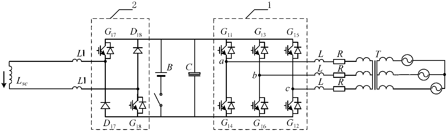
[0018] Embodiment 1, a large-capacity combined converter for electric energy storage, see figure 1 , including two-level three-phase voltage source converter 1, two-quadrant chopper 2 and superconducting inductor Lsc, the AC side of two-level three-phase voltage source converter 1 passes through grid-connected inductor L and lines, etc. The effective impedance R is connected to the multi-coil transformer T, and then connected to the power grid through the multi-output transformer T, the DC side is connected in parallel with the voltage stabilizing capacitor C and the equivalent battery B, and the two-quadrant chopper 2 and the two-quadrant chopper are connected in series 2. A bidirectional voltage source converter is formed by connecting the smoothing inductor L1 to the superconducting inductor Lsc.

[0019] When the superconducting magnet quenches, the equivalent battery B works, so that the energy is quickly transferred to the equivalent battery B without energy loss; the sm...

Embodiment 2

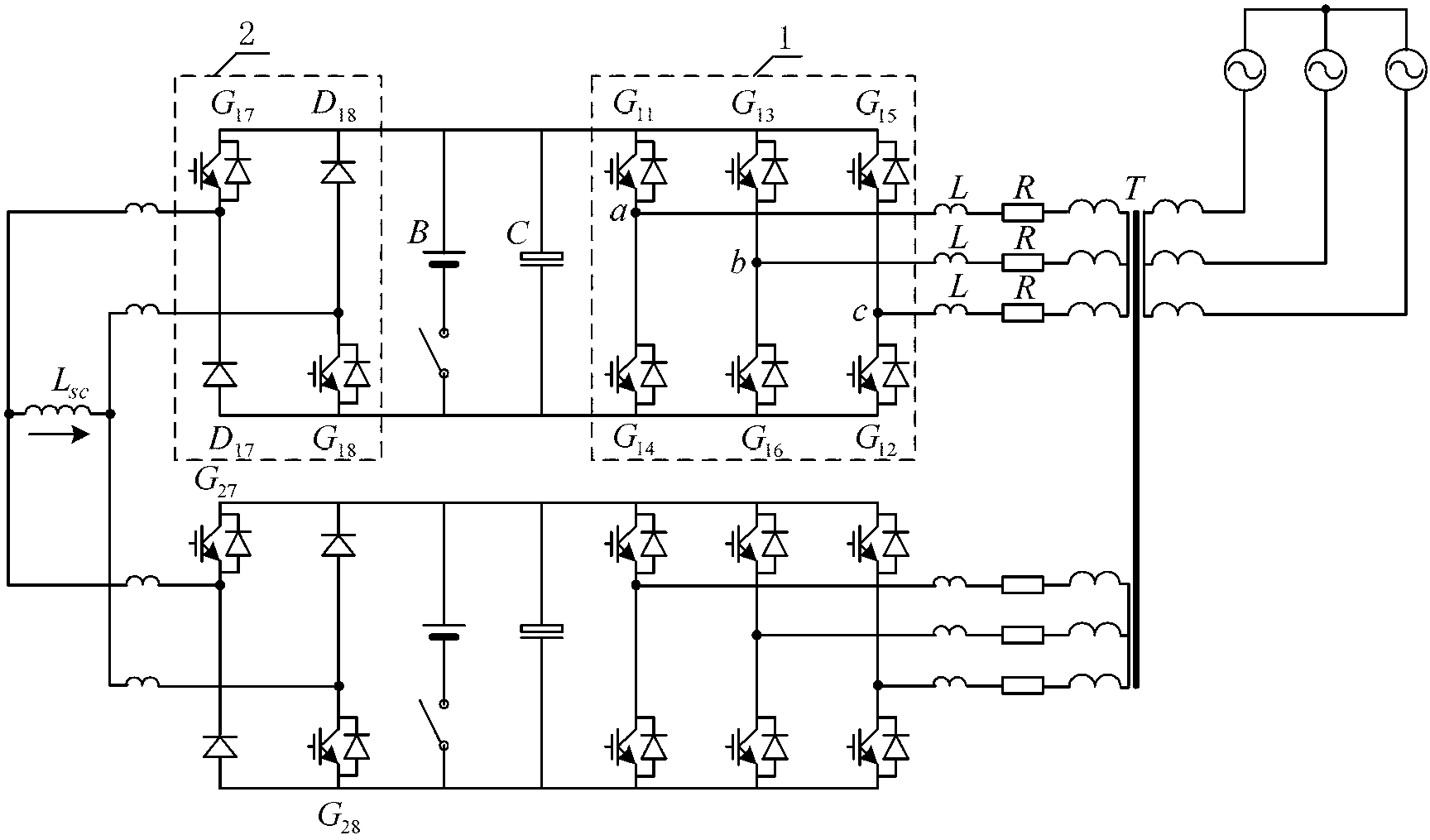
[0020] Embodiment 2, a large-capacity combined converter for electric energy storage, is a two-stage bidirectional voltage source converter, see figure 2 , composed of two bidirectional voltage source converters connected in parallel through superconducting inductance Lsc. Its structure is: a two-level three-phase voltage source converter 1, a two-quadrant chopper 2 and a superconducting inductor Lsc. The AC side of the two-level three-phase voltage source converter 1 passes through the grid-connected inductor L It is connected with the line equivalent impedance R and multi-coil transformer T, and then connected to the power grid through multi-output transformer T. The DC side is connected in parallel with a voltage stabilizing capacitor C and an equivalent battery B, and the two-quadrant chopper 2 is connected in series, and the two-quadrant The chopper 2 connects the smoothing inductor L1 and the superconducting inductor Lsc to form a bidirectional voltage source converter;...

Embodiment 3

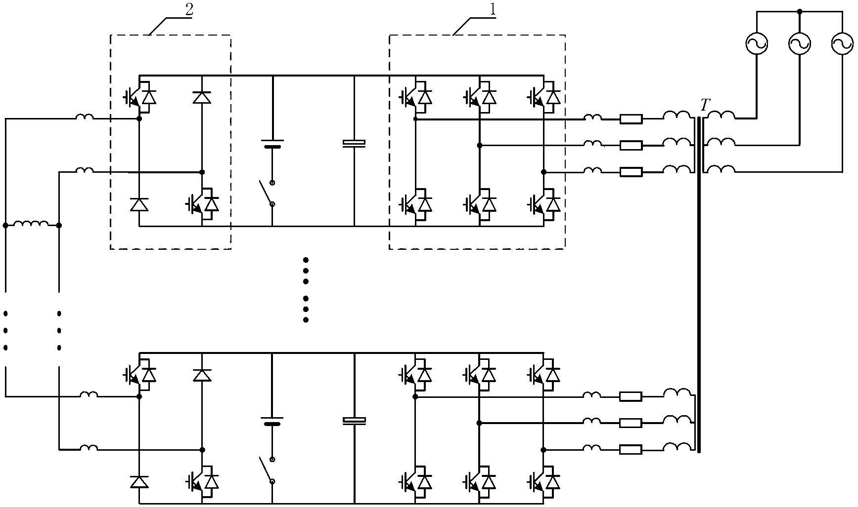
[0021] Embodiment 3, a large-capacity combined converter for electric energy storage is a three-level bidirectional voltage source converter, see image 3 , consists of three bidirectional voltage source converters connected in parallel, and its structure is: two-level three-phase voltage source converter 1, two-quadrant chopper 2 and superconducting inductor Lsc, two-level three-phase voltage The AC side of the source converter 1 is connected to the multi-coil transformer T through the grid-connected inductance L and the line equivalent impedance R, and then connected to the power grid through the multi-output transformer T, and the DC side is connected in parallel with the voltage stabilizing capacitor C and the equivalent battery B , and connect the two-quadrant chopper 2 in series, the two-quadrant chopper 2 is connected with the superconducting inductor Lsc through the smoothing inductor L1 to form a bidirectional voltage source converter; two-level three-phase voltage sou...


PUM


Abstract

The invention discloses a high-capacity combined converter used for the electric energy storage, comprising two-level three-phase voltage source type converters (VSC), a chopper and a superconducting inductor; alternating current sides of the two-level three-phase voltage source type converters are connected mutually through an equivalent inductance resistor LR, and then connected to a power grid through multiple groups of coil transformers T; direct current sides are linked to a voltage-stabilizing capacitor C and an equivalent storage battery B in parallel, and then linked with the two-quadrantal chopper in series; the two-quadrantal chopper is connected with the superconducting inductor through a flat wave inductor L1 to form a bidirectional voltage source type converter. For adopting the method of cascading two-level three-phase voltage source type converters and matching up with the chopper, the discharging and charging controls of the superconducting magnet are realized, the rapid flow of energy can be flexibly realized, and the harmonic wave content is effectively reduced; furthermore, the pressure resistance, the flow resistance and other problems of a switch tube in the process of high power conversion are solved, the circulation problem existing in the prior art is avoided, and the high power conversion is realized.

Description

technical field [0001] The invention relates to a large-capacity combined converter for electric energy storage, in particular to a voltage source converter for electric energy storage. Background technique [0002] Due to the increasing shortage of traditional energy sources and the deteriorating environment, with the discovery of high-temperature superconducting materials and the rapid development of power electronics technology, the application of superconducting energy storage (SMES) devices in power systems has become more and more extensive, which has also greatly promoted development of new energy. Most of the current power control devices for power energy storage are voltage source converters composed of power electronic switching elements. By controlling the amplitude and phase of the output voltage of the voltage source converter, it can quickly adjust the active power of the system. , Reactive power (including harmonics). However, the inherent randomness and int...

Claims


Application Information

Patent Timeline
Patent Type & Authority Applications(China)
IPC IPC(8): H02J3/38H02J3/32
CPCY02E40/67Y02E40/60
Inventor 张辉刘金虹李洁
Owner XIAN UNIV OF TECH
Why Eureka
Try Eureka