Transmitting end, receiving end, system and method for power line communication of contact network

A technology of power line communication and catenary, which is applied to the receiving end and the sending end of catenary power line communication, can solve the problems that have not been raised, and achieve the effect of being stable and widely distributed

Active Publication Date: 2012-10-03
BEIJING JIAODA MICROUNION TECH
View PDF3 Cites 15 Cited by
  • Summary
  • Abstract
  • Description
  • Claims
  • Application Information

AI Technical Summary

Problems solved by technology

[0012] It can be seen that, for the realization of signal transmission using the catenary, the traditional medium-voltage power l

Method used


Image

  • Transmitting end, receiving end, system and method for power line communication of contact network
  • Transmitting end, receiving end, system and method for power line communication of contact network
  • Transmitting end, receiving end, system and method for power line communication of contact network

Examples


Example Embodiment

[0070] Example 1

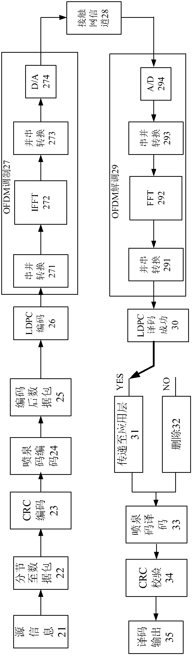
[0071] figure 2 It is a block diagram of the signal transmission system based on the contact network of the present invention. In the application layer frame of the sending end, the source information 21 is first segmented into the data packet 22, and then the functions of CRC encoding 23 and fountain code encoding 24 are realized, and then the encoded data packet 25 is obtained. Since the fountain code is decoded by continuously receiving the encoded information sent by the sender during the decoding 33, it does not have the function of checking the success of the decoding. It needs CRC to check whether the 34 data packet is completely and effectively decoded. The decoding process is terminated and the data packet is successfully decoded. Therefore, at the application layer, each data packet needs to be CRC encoded 23, CRC encoding 23, and fountain code encoding 24. What is implemented in the physical layer frame is the physical layer channel coding and OFDM...

Example Embodiment

[0076] Example 2

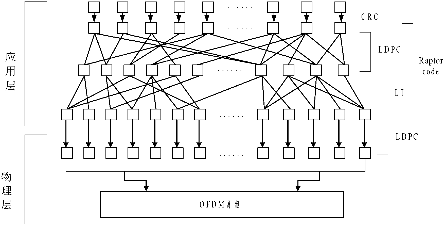
[0077] Such as Figure 2-4 As shown, the system transmits a frame of data, this frame of data contains N data packets, and the length of each data packet is k. Choose Raptor code as the application layer coding method.

[0078] 1) N data packets are first added with CRC check 23 at the application layer, and the length of each data packet is changed from k to l at this time. Then use the Raptor code formed by concatenating the LDPC code with the code rate of t and the LT code to encode 24, where the LDPC encoding in the Raptor code is performed between data packets, and the data packets are changed from N to R=N / t data package. Then perform LT encoding on K data packets in units of data packets, and set the decoding overhead of LT encoding to n, generally 0

[0079] 2) The physical layer coding uses an LDPC cod...


PUM


Abstract

The invention discloses a transmitting end, a receiving end, a system and a method for power line communication of a contact network and belongs to the technical fields of railway communication and urban rail communication. The transmitting end comprises the following modules including an application layer encoder, a physical layer encoder and a physical layer modulator, namely an OFDM (Orthogonal Frequency Division Multiplexing) modulator, wherein the application layer encoder is used for receiving source information and providing an encoding data stream; the application layer encoder comprises a CRC (Cyclic Redundancy Check) encoding and fountain code coding cascade; the physical layer modulator is used for receiving a data stream of the application layer encoder and has functions of forward error correcting and encoding; and the physical layer modulator is used for receiving a data stream of the physical layer encoder and generating an output signal by using an OFDM modulation mode. The invention further discloses a corresponding receiving end, a system and transmitting and receiving methods. Due to the combination of a fountain code cross-layer technology, a physical layer channel encoding and OFDM modulation technology, the problem of five kinds of noises of general power line communication is solved; and particularly due to the adoption of the fountain code cross-layer design, the problem that the on-off of a contact network channel and a current collector are intervened by electric spark pulse noise of the contact network is solved.

Description

technical field [0001] The invention relates to the technical field of railway signal communication and urban rail signal communication, in particular to a sending end, receiving end, system and method of catenary power line communication. Background technique [0002] The most important themes of railway transportation are safety and efficiency, and the signal communication system is an important prerequisite for improving efficiency and ensuring safety. At present, the vehicle-ground information transmission methods mainly include track circuits, track loops, leaky waveguides, inquiry transponders, and wireless communications. These traditional communication methods have their own advantages and disadvantages. The signal may be blocked due to factors such as geological structure, track pollution and corrosion, and locomotive traction current interference, or the signal equipment may fail due to external forces such as thunderstorms and mudslides. The currently disclosed t...

Claims


Application Information

Patent Timeline
IPC IPC(8): H04L1/00H04L27/26H04B3/54
Inventor 王文辉单冬张春明冯锡生
Owner BEIJING JIAODA MICROUNION TECH
Why Eureka
Try Eureka