LED (light emitting diode) light source subregion subsection transformation input driving control method and control circuit thereof

A technology of LED light source and control circuit, applied in the direction of light source, electric light source, energy-saving control technology, etc., can solve the problems of low light efficiency of lamps, different working hours of LED light-emitting tubes, low conversion efficiency, etc.

Inactive Publication Date: 2012-10-03
郑州信泽光电科技有限公司
View PDF4 Cites 15 Cited by
  • Summary
  • Abstract
  • Description
  • Claims
  • Application Information

AI Technical Summary

Problems solved by technology

According to this structure, when the AC power supply voltage is high, more LEDs can be lit, and when the AC voltage is small, fewer LEDs can be lit. There are two problems with this circuit: one is that the working time of the LED light-emitting tube is different, The duty cycle of the light-emitting tube that is turned on in the early stage can reach 0.9, while the duty cycle of the light-emitting tube that is turned on in the later stage is only 0.3-0.4, with an average of 0.55
Second, the light efficiency of lamps and lanterns is low
Although the conversion efficiency of the circuit is as high as 90%, the overall light efficiency is only 70%.
[0003] On May 22, 2010, the applicant filed an application for an invention patent for "Segmented Transformation Input AC Power Supply LED Light Source Drive Circuit". Although the LED balance can be increased to 90%, considering the feasibility of the circuit application and the The comprehensiveness of the power factor, the average duty cycle is only increased to 0.75, and the current and power of the light source must be increased to 1.4 times in order to reach the rated power.
However, the luminous efficiency working at 1.4 times the rated power is only 90% of the luminous efficiency working at the rated power. In addition to the circuit conversion efficiency, the overall efficiency from AC to light can only be 82%.
In the drive control method of the above two methods, the power conversion efficiency is determined according to the number of divided areas after the power supply is rectified. The more areas, the higher the conversion efficiency, and the less the area, the lower the conversion efficiency. The multi-area circuit structure is complex, and the control Many connections
like figure 1 The method shown in the existing LED light source segment input divides the power rectification area into 4 areas, and the LED light-emitting unit needs 3 groups, with only 3 working areas. The practicability of the two circuits does not meet the development of future LED lamps. Need, low power conversion efficiency, low light efficiency

Method used


Image

  • LED (light emitting diode) light source subregion subsection transformation input driving control method and control circuit thereof
  • LED (light emitting diode) light source subregion subsection transformation input driving control method and control circuit thereof
  • LED (light emitting diode) light source subregion subsection transformation input driving control method and control circuit thereof

Examples


Embodiment 1

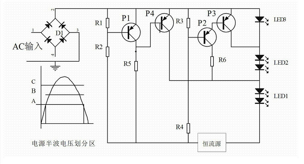
[0058] Embodiment 1: The LED light source of the present invention is partitioned and segmented into drive control methods. For 3 to 7 groups of LED light-emitting units with different conduction voltages, the conduction voltage of each group of LED light-emitting units is proportional. The LED light-emitting units In series and connected to the output terminal of the rectifier circuit through a constant current source circuit, the drive control method described above, 1) divides the output voltage of the rectifier circuit into 2 to 5 regions according to the waveform through the partition conversion input control circuit, and divides the high conduction voltage 2 to 6 groups of LED light-emitting units, according to the position of the region where the conduction voltage is located, the above-mentioned LED light-emitting units are driven in parallel, in series, or in series and parallel through the control circuit;

[0059]2) Combining with each of the above-mentioned division...

Embodiment 2

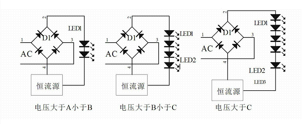
[0061] Embodiment 2: The driving control method of the LED light source in this embodiment is partitioned and segmented, and includes three groups of LED light emitting units, wherein the working voltage of the first group and the second group is 2u, and the working voltage of the third group is u. The half-wave cycle, partition conversion input control circuit is divided into 2 areas according to the instantaneous output voltage waveform of the rectifier circuit, and the segmental conversion input control circuit in the area divides each area into 2 sub-areas, and the LED light-emitting unit is controlled by the following method input,

[0062] 1) When the instantaneous output voltage of the rectifier circuit is less than 2u, all LED light-emitting units are not switched on;

[0063] 2) When the instantaneous output voltage of the rectifier circuit is greater than 2u but less than 3u, only the first group of LED light-emitting units is used;

[0064] 3) When the instantaneou...

Embodiment 3

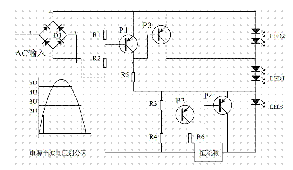
[0067] Embodiment 3: The LED light source of this embodiment is partitioned and segmented into drive control methods. The difference from Embodiment 2 is that on the basis of the method of Embodiment 2, the LED light-emitting units of the first group and the second group are passed through the unidirectional diode. connected, in each half-wave cycle, the subregional conversion input control circuit is divided into 2 regions according to the instantaneous output voltage waveform of the rectifier circuit, and the segmental conversion input control circuit in the region divides each region into 2 subregions, the same as described The partition conversion input control circuit is provided with a series-parallel conversion switch circuit, and the input of the LED light-emitting unit is controlled by the following method,

[0068] 1) When the instantaneous output voltage of the rectifier circuit is greater than 2u but less than 3u, the first group and the second group of LED light-em...


PUM


Abstract

The invention relates to a semiconductor lighting application technology, and discloses an LED (light emitting diode) light source subregion subsection transformation input driving control method and a control circuit thereof.. The control circuit is provided with 3-7 groups of LED glowing units with different break-over voltages. The control method is characterized in that (1) the subsection transformation input control circuit is used for dividing the output voltage of a rectifier circuit into 2-5 regions, and the 2-6 groups of LED glowing units with high voltage break-over voltages are driven in a parallel mode, or in a serial mode or in a combined parallel and serial mode through the control circuit according to the region positions of the break-over voltages; and (2), by combining each divided region, the 1-2 groups of the LED glowing units with low break-over voltages in the LED glowing units are enabled not to light in each divided region through control circuits in a driving mode, or a parallel driving mode or a serial driving mode. The combined efficiency of an LED light source can achieve more than 90%, the power supply conversion efficiency is high, meanwhile, an electrolytic capacitor is avoided being used, and the service life is long.

Description

technical field [0001] The invention relates to a semiconductor lighting application technology, in particular to a driving control method for LED light source partition and segment conversion input and a partition segment conversion input control circuit. Background technique [0002] Due to their remarkable advantages such as high luminous efficiency, obvious power-saving effect, long service life, no pollution, and anti-vibration, semiconductor lighting fixtures are increasingly valued by countries all over the world, and are expected to replace various traditional lighting fixtures in the near future. However, the current LED light source lighting lamps are usually powered by DC power supply. In daily applications, a constant current drive power supply that converts AC power into DC power must be installed in the lamp. Although the output of the current switching constant current source is stable, its power circuit is usually Unavoidable use of electrolytic capacitors. ...

Claims


Application Information

Patent Timeline
Patent Type & Authority Applications(China)
IPC IPC(8): H05B37/02
CPCY02B20/42Y02B20/40
Inventor 李云霄云永利
Owner 郑州信泽光电科技有限公司
Why Eureka
Try Eureka