
Airlifting multistage staggered circulation flow tower and circulation flow structure

A cyclic flow, air lift technology, applied in chemical methods, chemical instruments and methods, chemical/physical processes, etc., for the reaction of liquid and gas medium, which can solve the problem of poor mass transfer between phases and cannot reflect multi-stage circulating flow advantages, inadequate exposure to mixing, etc.

Active Publication Date: 2012-10-10
TIANJIN UNIV
View PDF3 Cites 7 Cited by
  • Summary
  • Abstract
  • Description
  • Claims
  • Application Information

AI Technical Summary

Problems solved by technology

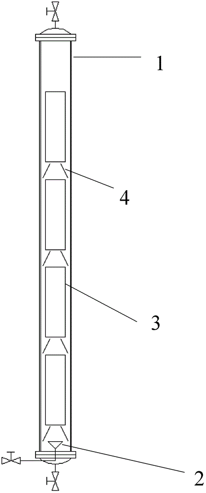
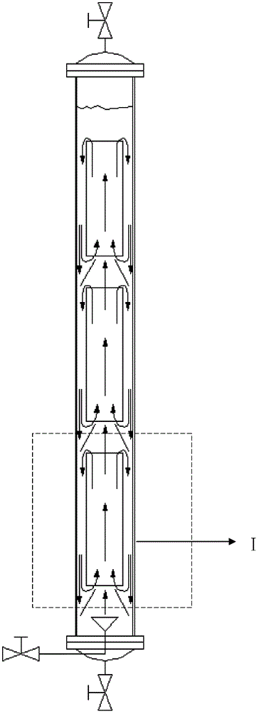
The flow conditions in the tower are as follows figure 2 As shown in -I, the gas drives the fluid in the central tube (3) to flow upwards, and the gas holdup in the tube is greater than the annulus, that is, the density of the fluid in the annulus is greater than that in the tube, which pushes the liquid to circulate downwards back into the central tube, so that the fluid forms a "pipe rise-ring" There is only one type of circulation flow (I), because there is only one form of circulation flow, and the fluids between the stages are in contact with each other along the flow, without sufficient contact and mixing, and the mass transfer between the phases is poor, which cannot reflect the advantages of multi-stage circulation flow

Method used


Image

  • Airlifting multistage staggered circulation flow tower and circulation flow structure
  • Airlifting multistage staggered circulation flow tower and circulation flow structure
  • Airlifting multistage staggered circulation flow tower and circulation flow structure

Examples


Embodiment Construction

[0017] Below in conjunction with accompanying drawing, the present invention is described in further detail:

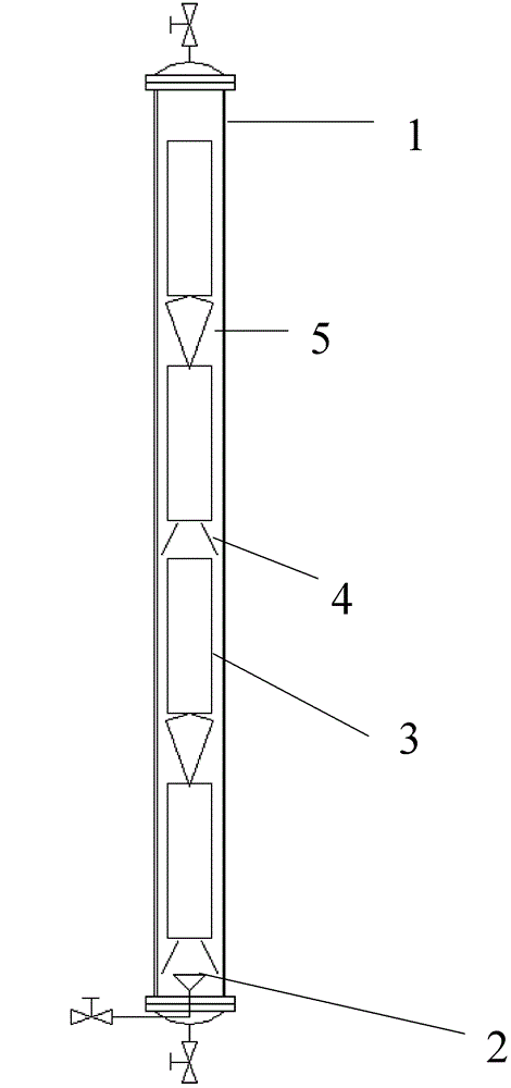
[0018] Such as image 3 As shown, the air-lift multi-stage staggered circulation flow tower consists of a tower body (1), a microbubble gas generator (2), a multi-stage center pipe (3), an annulus to the center guide tube (4), a center to the center Annulus guide tube (5) and other parts constitute. The tower body (1) is provided with a multi-section center pipe, and under the multi-section center pipe, an annular gap to the center guide tube (4) or a center to the center annular gap guide tube (5) is arranged at intervals, and the annular gap guides the flow to the center The cylinders (4) and the center-to-annulus guide cylinders (5) are placed alternately under the multi-stage center pipe (3).

[0019] The tower body used in this example has a diameter of 150mm and a height of 3000mm. Four sections of central tubes are used. The diameter of the central tube is 11...


PUM

PropertyMeasurementUnit
Diameteraaaaaaaaaa

Abstract

The invention relates to an airlifting multistage staggered circulation flow tower and a circulation flow structure. The structure of the circulation flow tower comprises a tower body, a microbubble gas generator, multistage central tubes, annular clearance toward centre draft tubes, and centre toward annular clearance draft tubes, wherein the multiple central tubes are arranged in the tower body, the annular clearance toward centre draft tubes or the centre toward annular clearance draft tubes are arranged below the multiple central tubes, and the annular clearance toward centre draft tubes or the centre toward annular clearance draft tubes are arranged alternately under the multiple central tubes. The annular clearance toward centre draft tubes introduces rising gas from a lower stage into the central tubes to form a circulation flow of fluid ''rising in central tubes, falling in annular clearances'', the centre toward annular clearance draft tubes introduces gas into the annular clearances between the outside of the central tubes and the tower body to form a circulation flow of fluid ''rising in annular clearances, falling in central tubes''. According to the invention, the mixing and transmission are strengthened; the gas holdup can be increased 20%-40%, and the bubble distribution consistency degree can be increased 10%-30% in a comparison with a traditional multistage airlifting circulation flow tower using only annular clearance toward centre draft tubes.

Description

technical field [0001] The invention relates to an air-lift multi-stage interleaving circulation flow tower and a circulation flow structure, in particular to an air-lift multi-stage circulation flow structure flow tower with fluid interlacing flow between stages and interphase countercurrent contact and mixing fully. Applicable to chemical industry, metallurgy, wastewater treatment and other fields. Background technique [0002] Air-lift circulating flow towers are widely used in air-lift loop reactors in chemical and energy fields, as well as flotation columns in metallurgy and wastewater treatment fields. Traditional mechanically stirred reactors and flotation machines have the disadvantages of high energy consumption and complex structure, which is not conducive to maintenance. The principle of the air-lift circulating flow tower is that after the gas enters the ascending pipeline, the density difference caused by the different gas holdup inside and outside the tube pro...

Claims


Application Information

Patent Timeline
IPC IPC(8): B01J10/00
Inventor 刘春江郄思远鲍银龙袁希钢
Owner TIANJIN UNIV
Learn More