Full vibration discharge silo and silo vibration discharge method
A technology of discharging barrel and vibrating hopper is applied in the field of full vibrating discharging silo and vibrating discharging of silo, which can solve the problems of long occupation of warehouse wharf, easy corrosion of screw cleaning machine, affecting the overall operation of storage, etc. Solving the problem of spontaneous combustion, ideal ventilation effect, and improving the utilization rate of social resources
- Summary
- Abstract
- Description
- Claims
- Application Information
AI Technical Summary
Problems solved by technology
Method used
Image
Examples
Embodiment 1
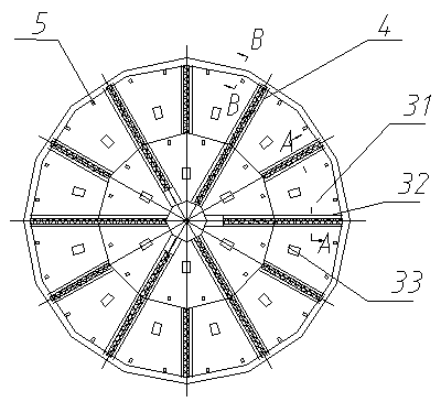
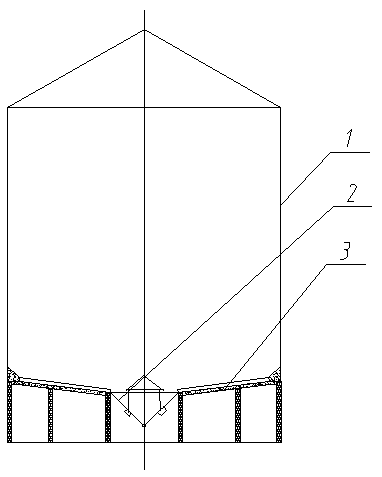
[0044] The full-vibration discharge silo includes a silo body 1, a silo top located at the upper part of the silo body and a silo bottom at the bottom. The center of the silo bottom has a conical vibrating hopper 2, and a group of vibrating hoppers are radially distributed around the conical hopper. Disk 3 , the vibration disk includes a disk 31 , a frame 32 and a vibration motor 33 .
[0045] The disc is supported by the bottom of the bin and falls on the bottom of the bin.
[0046] The discs can also drop onto the bottom of the bin through a transition piece.
[0047] The vibration motor is installed above the disc, and can also be installed at the bottom of the vibrating plate.
[0048] The vibrating plate is inclined towards the center of the warehouse bottom.
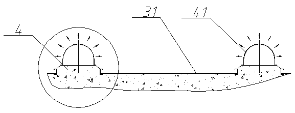
[0049] Adjacent vibrating plates are bordered by the deflector 4, may also be bordered by the frame body 32, and may also be used in combination.
[0050] Hopper vibrating motor 6 is housed outside the conical v...
Embodiment 2
[0052] In the full vibration discharging silo described in Embodiment 1, the vibrating plate frame 32 includes three sides located at the high position and two sides of the disc, and there is no frame on the low side of the vibrating plate, It is a dustpan-shaped concave structure with three frames that is open on one side. The disc is trapezoidal and can also be a section of a ring. The length of the side at a higher position should generally be less than 8m. The vibrating plate is inclined to the central discharge position of the bottom of the bin, and the inclination angle is more than 2°, preferably between 5°-15°.
Embodiment 3
[0054] In the above-mentioned full-vibration discharge silo, the disc 31 is formed by connecting two or more steel plates through threaded connectors or threaded connectors with cotter pins. This assembled structure is convenient for transportation, and is more convenient than welding. More resistant to vibration.
[0055] The inclination angle of the disk to the center of the bottom of the bin can be between 8°-11°, and the transition piece is a spring.
[0056] If it is used as a storage bin for food crops, especially oil crops, or other crops that are easy to harden, some of the vibrating plates are anti-hardening, anti-bridging and anti-arching vibrations with large power but smaller single area. As for the discs, the vibrating discs for anti-hardening, anti-bridging and anti-arching can be arranged adjacent to each other in a concentrated manner or at intervals.
PUM
 Abstract
Description
Claims
Application Information
 - R&D
- Intellectual Property
- Life Sciences
- Materials
- Tech Scout
- Unparalleled Data Quality
- Higher Quality Content
- 60% Fewer Hallucinations
Browse by: Latest US Patents, China's latest patents, Technical Efficacy Thesaurus, Application Domain, Technology Topic, Popular Technical Reports.
© 2025 PatSnap. All rights reserved.Legal|Privacy policy|Modern Slavery Act Transparency Statement|Sitemap|About US| Contact US: help@patsnap.com


