Steel beam grid floor formwork system

A technology for floor slabs and steel beams, applied in the field of tooling equipment, can solve the problems of less turnover, long erection time, weak bonding force, etc., and achieve the effect of improving surface hardness, more turnover times, and enhancing bonding force

Inactive Publication Date: 2012-10-10
CHINA CONSTR FIRST DIV GROUP CONSTR & DEV
View PDF5 Cites 11 Cited by
  • Summary
  • Abstract
  • Description
  • Claims
  • Application Information

AI Technical Summary

Problems solved by technology

The disadvantages of this system are: the poplar boards of ordinary panels are soft and easy to break, resulting in an uneven pouring surface, the urea-formaldehyde resin glue used in the multi-layer boards has weak adhesion, and the glue between the multi-layer boards is easy to open and deform when it meets water, resulting in poor quality , the format is large and difficult to carry, and it is easy to be bumped and damaged when carrying it. Therefore, the traditional multi-layer panel has fewer turnover times, resulting in a high cost of templates per square meter of construction. In addition, urea-formaldehyde resin glue is highly toxic. Therefore, the traditional multi-layer panel The less turnover times, the greater the environmental pollution hazards; the wooden keel has a short service life and is manually sawed and cut on site, so the cutting is very random, so the material loss is large and the project cost is increased; fastener-type steel pipe scaffolding The quantity of supporting steel per unit building area is large, and the erection time is long, resulting in high project cost
Due to the complex and dense structural parts of the traditional formwork system, it is not convenient to carry out the project quality and safety acceptance after completion

Method used


Image

  • Steel beam grid floor formwork system
  • Steel beam grid floor formwork system
  • Steel beam grid floor formwork system

Examples


Embodiment Construction

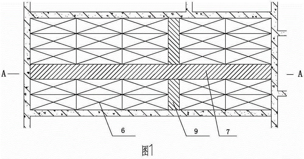
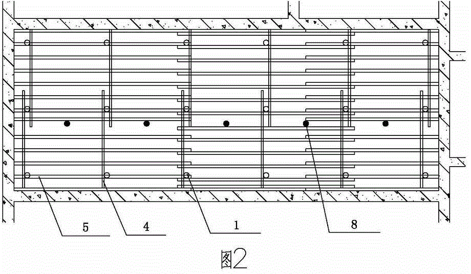
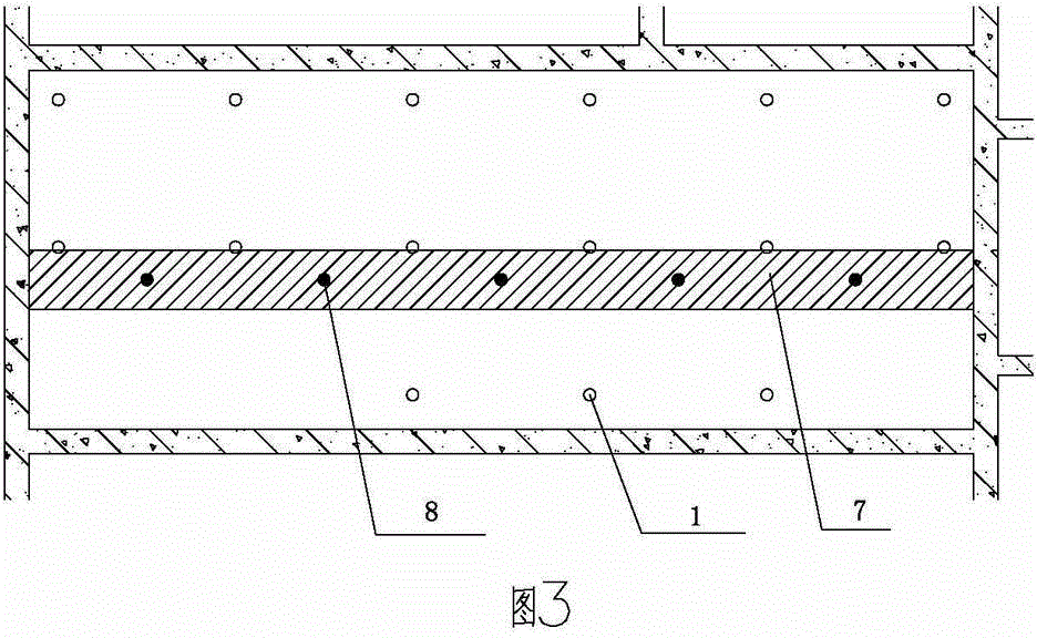
[0033] Such as Figure 1 to Figure 5 As shown, the steel girder grid floor formwork system of the present invention is arranged symmetrically with some independent early demolition steel supports 1 in some horizontal rows and some vertical rows on the bottom floor, and is evenly distributed in a vertical row. A number of independent late-demolition steel supports 8 are set, and inner sleeves 1-2 are provided on each independent early-demolition steel support 1, and jacking brackets 3 are provided on the top of the inner sleeves 1-2. Several rows of square steel beams 4 are horizontally laid on the jacking 3 of the steel support 1, and several rows of several-shaped steel beams 5 are evenly distributed longitudinally on several horizontal rows of square steel beams 4. The notches of the several-shaped steel beams 5 face upward and are fixed in the groove There are wooden squares, several new panels 6 are laid on the several-shaped steel beams 5, and the new panels 6 are fixed o...


PUM


Abstract

The invention provides a steel beam grid floor formwork system, wherein a plurality of early removed steel supports and a plurality of late removed steel supports are evenly arranged on a bottom floor; the top end of an internal sleeve of each early removed steel support is provided with a jack; a plurality of rows of square steel beams are paved on the jacks in the transverse direction; and a plurality of rows of n-shaped steel beams are evenly arranged on the square steel beams in the longitudinal direction; faceplates are paved on the n-shaped steel beams; all the faceplates are arranged between collected strip clearances; late removed strips are paved in the longitudinal direction; and clearance plates are paved in the transverse direction; the bottom faces of the late removed strips are directly supported by the late removed steel supports; and longitudinal and transverse horizontal steel pull rods are buckled with the internal sleeves of all the steel supports through fasteners. Having the serialized structure sizes, the n-shaped steel beams, the square steel beams and the faceplates are convenient to use, and have great structural strength and high safety coefficient; and additionally, the n-shaped steel beams, the square steel beams and the faceplates are difficultly damaged so as to be reused for multiple times. The new type faceplates are low in toxicity and great in surface hardness, and are reused for multiple times which are three times that of the traditional faceplates. When the steel beam grid floor formwork system is used, the construction speed is high, the materials and the woods are saved, the environmental pollution level is low, less support steel is used, and the project cost is low.

Description

technical field [0001] The invention relates to tooling equipment in building construction, in particular to a steel beam grid floor formwork system for construction of cast-in-place reinforced concrete floor slab structures in building construction. Background technique [0002] At present, the formwork system used in the construction of cast-in-place reinforced concrete slabs is an ordinary multi-layer panel with a specification of 1220mm×2440mm or 915mm×1830mm, a wooden square keel with a specification of 100mm×100mm, 50mm×100mm, fasteners of Φ48mm×3.5mm and Fastener-type steel pipe scaffolding as a supporting system. The disadvantages of this system are: the poplar boards of ordinary panels are soft and easy to break, resulting in an uneven pouring surface, the urea-formaldehyde resin glue used in the multi-layer boards has weak adhesion, and the glue between the multi-layer boards is easy to open and deform when it meets water, resulting in poor quality , the format is...

Claims


Application Information

Patent Timeline
Patent Type & Authority Applications(China)
IPC IPC(8): E04G11/42E04G11/48E04G11/50E04G25/06
Inventor 高俊峰侯本才陈学跟黄勇刘录胡文俊
Owner CHINA CONSTR FIRST DIV GROUP CONSTR & DEV
Why Eureka
Try Eureka