
Hydraulic ventilation energy-saving cooling tower with intelligent compensation device

A compensation device and ventilated technology, which is applied in the field of hydraulic ventilated energy-saving cooling towers, can solve the problems of low efficiency, thermal performance of cooling towers that cannot meet the requirements of the process, and high energy consumption, so as to achieve high cooling efficiency and save hydraulic kinetic energy , the effect of avoiding pollution

Inactive Publication Date: 2012-10-10
王志成
View PDF7 Cites 0 Cited by
  • Summary
  • Abstract
  • Description
  • Claims
  • Application Information

AI Technical Summary

Problems solved by technology

[0003] Mechanical ventilation cooling tower: its disadvantages are: low efficiency and high energy consumption, because the energy input into the cooling tower has two aspects: one is the electric energy input by the motor reducer, and the other is input from the water pipe entering the tower to the water distribution sprinkler water energy
But in summer, the energy required by the fan of the cooling tower must be large enough, and the abundant water energy cannot meet the needs of the fan speed, resulting in the thermal performance of the cooling tower not meeting the requirements of the process

Method used


Image

  • Hydraulic ventilation energy-saving cooling tower with intelligent compensation device
  • Hydraulic ventilation energy-saving cooling tower with intelligent compensation device
  • Hydraulic ventilation energy-saving cooling tower with intelligent compensation device

Examples


Embodiment 1

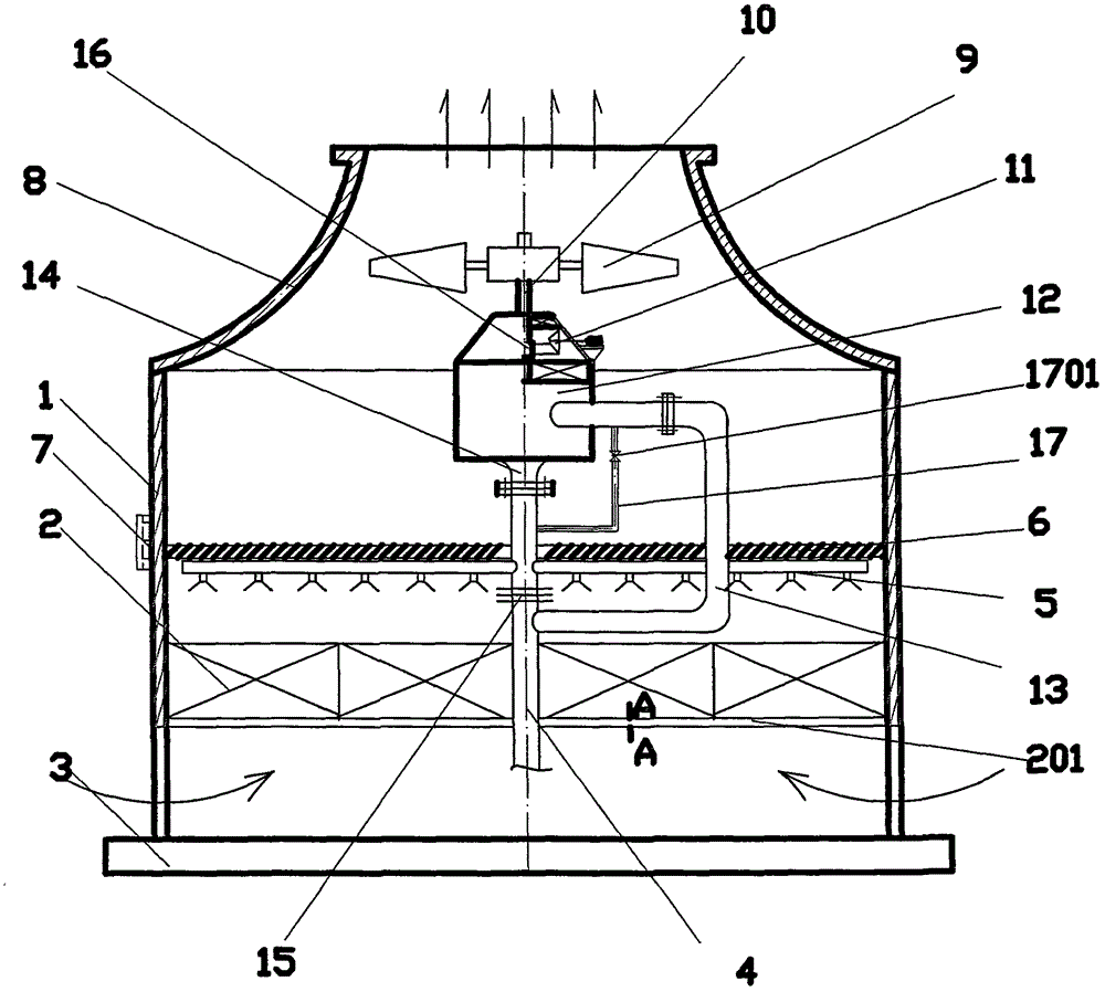
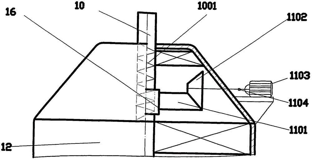
[0021] A hydraulic ventilated energy-saving cooling tower with an intelligent compensation device, comprising: an automatic controller, a water spraying filler 2 arranged inside the tower body 1, a water collection pool 3 arranged under the tower body 1, a water eliminator 6 and a water distribution spray device arranged inside the tower 5. The water distribution and spraying device 5 is connected to the tower water pipe 4, and the fan 9 is arranged in the air cylinder 8 at the top of the tower body 1. The tower water pipe 4 is connected to the hydraulic propeller 12 through the hydraulic propeller water inlet pipe 13, and the hydraulic propeller The water inlet pipe communicates with the hydraulic propeller decompression device 17, and the hydraulic propeller decompression device 17 communicates with the hydraulic propeller outlet pipe 14 through a pressure reducing valve 1701; the impeller output shaft 10 of the hydraulic propeller 12 is connected to the blower fan 9, and it i...


PUM


Abstract

The invention discloses a hydraulic ventilation energy-saving cooling tower with an intelligent compensation device. The hydraulic ventilation energy-saving cooling tower comprises an automatic controller, wherein packing is arranged in a tower body; a water collection tank is arranged below the tower body; a water collector and a water distributing and spraying device are arranged in the tower; the water distributing and spraying device is communicated with a tower inlet water tube; a fan is arranged in an air tube on the top of the tower body; the tower inlet water tube is communicated with a hydraulic thruster through a hydraulic thruster water inlet tube; the hydraulic thruster water inlet tube is communicated with a hydraulic thruster pressure reducing device; the hydraulic thruster pressure reducing device is communicated with a hydraulic thruster water outlet tube through a pressure reducing valve; and an impeller output shaft of the hydraulic thruster is connected with the fan. The hydraulic ventilation energy-saving cooling tower is characterized in that the impeller output shaft is provided with an intelligent rotating speed compensation device, wherein according to the intelligent rotating speed compensation device, the impeller output shaft is connected with a conical gear ring through an overrunning clutch; the conical gear ring is meshed with a bevel pinion; and the bevel pinion is connected with a motor. As the hydraulic ventilation energy-saving cooling tower has an automatic flow production line, the cooling effect always can meet the requirements of thermal performance. The hydraulic ventilation energy-saving cooling tower is high in cooling efficiency, low in failure rate in the working process, energy-saving and environment-friendly.

Description

technical field [0001] The invention relates to a hydraulic ventilation type energy-saving cooling tower with an intelligent compensation device. Background technique [0002] There are currently two types of cooling towers: one is a mechanical ventilation cooling tower, and the other is a hydraulic ventilation cooling tower. [0003] Mechanical ventilation cooling tower: its disadvantages are: low efficiency and high energy consumption, because the energy input into the cooling tower has two aspects: one is the electric energy input by the motor reducer, and the other is input from the water pipe entering the tower to the water distribution Sprinklers for spraying water. The input of these two energies needs to be relatively large. At the same time, the noise of the cooling tower is proportional to the fifth power of the fan speed. This kind of cooling tower is noisy and pollutes the surrounding environment greatly. [0004] And the general hydraulic ventilation cooling...

Claims


Application Information

Patent Timeline
Patent Type & Authority Applications(China)
IPC IPC(8): F28F27/00F03B13/00
CPCY02P80/10
Inventor 王志成王金勇尹政周长西
Owner 王志成
Learn More