Method for setting fixed-time power on and off of electrical appliance device with microprocessor

A microprocessor and timing switch technology, which is applied to program control and electrical program control in sequence/logic controllers, can solve the problems of increased buttons, settings, and large display space, and achieves simplified circuit structure, Set precise effects

Inactive Publication Date: 2012-10-10
宁波毕士达智能洁具有限公司
View PDF5 Cites 7 Cited by
  • Summary
  • Abstract
  • Description
  • Claims
  • Application Information

AI Technical Summary

Problems solved by technology

[0002] Now more and more electrical appliances have the function of timing switch. The setting of the existing timing switch generally requires a display screen showing the current time and the set time, a real-time clock circuit, and multiple special timing setting buttons. To complete the completion, the circuit structure of the electrical appliance is cumbersome, the display screen takes up a lot of space, and the number of buttons is increased, and generally only one switch can be set, and it is impossible to set the switch for multiple periods. Turn on at 6:00, but it is impossible to set multiple actions such as turning off the appliance at 10:00 and restarting at 12:00, so that it is impossible to accurately control the switching time of the appliance, and the best energy-saving effect cannot be achieved.

Method used


Image

  • Method for setting fixed-time power on and off of electrical appliance device with microprocessor

Examples


Embodiment 1

[0028] The setting method and application of the present invention will be described below with an intelligent toilet.

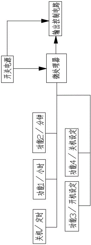
[0029] The microprocessor of the smart toilet is equipped with a multi-period timer switch setting program, which can accurately control the switch time of the smart toilet. For example, the user requires the smart toilet to be turned on at 12:00 on the same day and turned off at 13:10. Turn on at 18:00, turn off at 20:00, turn off at 6:30 the next day, turn off at 7:30, the setting steps are as follows:

[0030] The first step is to enter the timing setting mode: press and hold the off button for 6 seconds, the timing switch setting indicator light will light up, prompting the system to enter the timing setting mode, at this time, the massage button, the powerful flushing button, the buttock button on the original smart toilet The functions of the cleaning key and the women's cleaning key are changed to the hour key, minute key, power off setting key, and p...

Embodiment 2

[0040] In the same way, you can also set the smart toilet to turn off at 12:00 on the same day, turn on at 13:10, turn off at 18:00, turn on at 20:00, turn off at 6:30 the next day, turn on at 7:30, set Proceed as follows:

[0041] The first step, with embodiment one;

[0042] The second step is to set the first shutdown time: calculate the time interval from the current time (if the current time is 9:30 am) to 12:00 o'clock shutdown as 2 hours and 30 minutes, press the hour key twice at this time , the microprocessor counts for 2 hours, then press the minute button 3 times, the microprocessor counts for 30 minutes, at this time the microprocessor counts for 2 hours and 30 minutes in total, press the shutdown setting button at this time, and 2 After 30 minutes (that is, at 12:00 on the same day), the system will automatically shut down;

[0043] The third step is to set the first power-on time: press the hour button once, then press the minute button once, the microprocessor...


PUM


Abstract

The invention discloses a method for setting fixed-time power on and off of an electrical appliance device with a microprocessor, which is suitable for a device with the microprocessor. An applied device comprises a key control circuit, a switch power supply, the microprocessor and an output control circuit, wherein the key control circuit comprises a power off key and four function keys. The method comprises the following steps of: (1) powering on the microprocessor; (2) switching the functions of keys; (3) setting multi-period timing; and (4) determining whether the timing setting is completed or not, and timing by a system; and presetting a circulation time T1 by the system. According to the method disclosed by the invention, the setting for the fixed-time power on and off in multiple periods can be carried out, the keys are not added, and a display screen and a real-time clock circuit are not needed.

Description

technical field [0001] The invention relates to an automation technology processing process, in particular to a method for setting a timing switch of an electrical device with a microprocessor. Background technique [0002] Now more and more electrical appliances have the function of timing switch. The setting of the existing timing switch generally requires a display screen showing the current time and the set time, a real-time clock circuit, and multiple special timing setting buttons. To complete the completion, the circuit structure of the electrical appliance is cumbersome, the display screen takes up a lot of space, and the number of buttons is increased, and generally only one switch can be set, and it is impossible to set the switch for multiple periods. Turn on at 6 o'clock, but it is impossible to set multiple actions such as turning off the appliance at 10 o'clock and turning it on again at 12 o'clock, so that it is impossible to accurately control the switching t...

Claims


Application Information

Patent Timeline
Patent Type & Authority Applications(China)
IPC IPC(8): G05B19/04
Inventor 李爱良张秀军仇世达
Owner 宁波毕士达智能洁具有限公司
Why Eureka
Try Eureka