Oscillation testing device of servo motor of numerical control machine tool

A test device and servo motor technology, applied in the mechanical field, can solve problems such as difficult to judge, not obvious vibration, motor vibration, etc., and achieve the effect of easy installation

Inactive Publication Date: 2012-10-10
GUANGXI UNIVERSITY OF TECHNOLOGY +3
View PDF4 Cites 1 Cited by
  • Summary
  • Abstract
  • Description
  • Claims
  • Application Information

AI Technical Summary

Problems solved by technology

[0003] The use of the servo motor must match the quality of the drive, so in the CNC machine tool, it is necessary to adjust the parameters of the servo motor, otherwise it is easy to cause motor oscillation, especially when the full-closed-loop servo drive of the grating scale is used, due to the servo motor encoder and the grating scale When the compensation does not match, it is more likely to cause motor vibration, but the vibration at this time is generally not obvious. In the past, it was mostly judged by experience or by observing the surface roughness of the workpiece through finishing machining; when testing with test tools such as acceleration sensors, due to its judgment The principle is to use the piezoelectric effect, and the vibration caused by the normal operation of the machine tool and the vibration caused by the vibration of the servo motor will produce this effect. Therefore, it is difficult to judge whether it is the vibration of the machine tool itself or the vibration caused by the vibration of the servo motor

Method used


Image

  • Oscillation testing device of servo motor of numerical control machine tool
  • Oscillation testing device of servo motor of numerical control machine tool
  • Oscillation testing device of servo motor of numerical control machine tool

Examples


Embodiment Construction

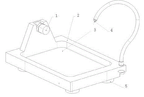
[0025] The following is attached figure 1 An embodiment of the invention is described:

[0026] The test tool body 2 is equipped with an acceleration sensor 1 and a shallow pool 3. A layer of 20# engine oil is placed in the shallow pool 3. The adjustable camera 4 is facing the liquid surface. The height is just enough to take a picture of the liquid surface. The magnetic base 5 is used under the test tool body to form a stable connection with the working platform of the machine tool, and it moves with the feed movement of the working platform of the machine tool.

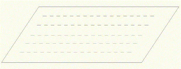
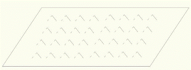
[0027] When the CNC machine tool is started, the liquid level fluctuation of 20# engine oil captured by the adjustable camera 4 is transmitted to the computer for observation, and it is judged whether it is the vibration of the servo motor. If it is confirmed that the vibration is caused by the vibration of the servo motor, the acceleration The time-domain and frequency-domain signals tested by sensor 1 are analyz...


PUM


Abstract

The invention provides an oscillation testing device of a servo motor of a numerical control machine tool. The oscillation testing device comprises a computer, an adjustable camera, a testing tool body and fixing devices, the testing tool body comprises a shallow tank, a solution with the kinematic viscosity of 0.6x10<-3>pa.s-50x10<-3>pa.s at temperature of 40 DEG C is contained in the shallow tank, the adjustable camera directly faces to the solution level, the height of the camera is adjusted to a level by which the cameral can just take a complete picture of the solution level, changes of the solution level are monitored by computer videos, and oscillation of the servo motor can be quantifiably tested by a speed sensor mounted on the testing tool body. The problem of difficulty in distinguishing vibration of the numerical control machine tool from vibration caused by oscillation of the servo motor in the prior art is solved by the oscillation testing device, and the oscillation testing device of the servo motor of the numerical control machine tool has good application prospect.

Description

technical field [0001] The invention relates to the mechanical field, in particular to a vibration testing device for a servo motor of a numerically controlled machine tool. Background technique [0002] At present, the acceleration sensor is mainly used to test the vibration of the machine tool in the machine tool industry, and its principle is mainly based on the principle of piezoelectric effect. The so-called piezoelectric effect is "for a heteropolar crystal without a symmetry center, the external force applied to the crystal will not only deform the crystal, but also change the polarization state of the crystal, and establish an electric field inside the crystal. The phenomenon of polarizing the medium is called the positive piezoelectric effect". The acceleration sensor used in the machine tool industry mainly utilizes the characteristic of crystal deformation caused by acceleration inside it. Since this deformation will generate a voltage, as long as the relationsh...

Claims


Application Information

Patent Timeline
Patent Type & Authority Applications(China)
IPC IPC(8): G05B19/406
Inventor 莫翔明尹辉俊许冠能宋世柳叶文龙
Owner GUANGXI UNIVERSITY OF TECHNOLOGY
Why Eureka
Try Eureka