Alternating current-to-direct current circuit

A technology of alternating current to direct current and rectification circuit, which is applied in the direction of irreversible alternating current power input conversion to direct current power output, direct current power input conversion to direct current power output, electrical components, etc., which can solve the problem of low circuit efficiency, large switching loss, high cost, etc. problem, to achieve the effect of improving conversion efficiency, increasing duty cycle, and reducing electrical stress

Inactive Publication Date: 2012-10-10
MORNSUN GUANGZHOU SCI & TECH
View PDF4 Cites 17 Cited by
  • Summary
  • Abstract
  • Description
  • Claims
  • Application Information

AI Technical Summary

Problems solved by technology

[0010] The common BUCK circuit is used in the occasion of pulsating DC input. When the voltage of the input pulsating DC reaches the peak value, the duty cycle reaches the minimum, the switching loss is large, and there are disadvantages of low circuit efficiency and large loss.
[0011] "An AC-to-DC Circuit" of Chinese Patent Application No. 201210056555 shows an AC-to-DC circuit for low-power applications. It is used for applications with output power above 3W, and it also has many current harmonics and low efficiency. shortcoming
[0014] For the two-stage scheme of using BOOST's PFC plus DC / DC, there are also disadvantages of complex circuits and high costs.

Method used


Image

  • Alternating current-to-direct current circuit
  • Alternating current-to-direct current circuit
  • Alternating current-to-direct current circuit

Examples


no. 1 example

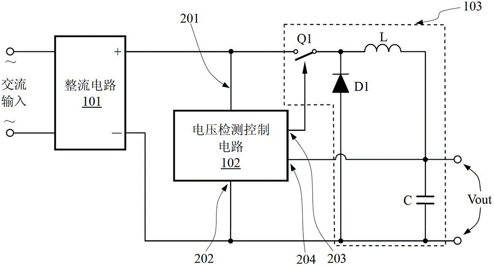
[0043] figure 2 A schematic block diagram of the first embodiment of the present invention is shown, and the AC to DC circuit includes a rectification circuit 101 , a voltage detection control circuit 102 , and a BUCK circuit 103 .

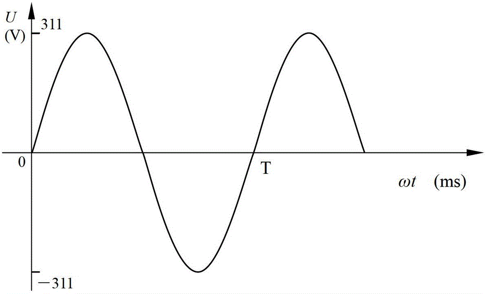
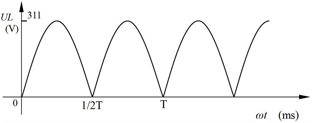
[0044] The rectification circuit 101 rectifies the input alternating current and outputs pulsating direct current, see image 3 , the horizontal axis is the time axis, T represents the period of the input alternating current, and the vertical axis is the instantaneous voltage value of the pulsating direct current; the voltage detection control circuit 102 detects the instantaneous value of the pulsating direct current through the port 201 and the port 202, and simultaneously detects the voltage of the low-voltage output terminal through the port 204 Output voltage Vout, and output PWM signal through port 203 to control switch Q1 in BUCK circuit 103; switch Q1 is usually a MOS tube.

[0045] The BUCK circuit 103 is connected after the rectifier cir...

no. 2 example

[0068] Figure 6 It is the principle diagram of the second embodiment of the present invention. The AC-to-DC circuit of the second embodiment includes a rectifier circuit 101, a voltage detection control circuit 102, and a BUCK circuit 103; on the basis of the first embodiment, the BUCK circuit The freewheeling diode D1 is replaced by an N-channel MOS transistor Q2, and the MOS transistor Q2 plays the role of freewheeling here. The conduction voltage is reduced, so the conversion efficiency of the whole machine is high.

[0069] The rectification circuit 101 rectifies the input alternating current and outputs pulsating direct current, see image 3 The voltage detection control circuit 102 detects the instantaneous value of the pulsating direct current through the port 201 and the port 202, and simultaneously detects the output voltage Vout of the low-voltage output terminal through the port 204, and simultaneously outputs the PWM signal through the port 203 to control the swi...

no. 3 example

[0085] Figure 7 The schematic diagram of the third embodiment of the present invention is shown. As is known, the flyback circuit is a modification of the BUCK circuit, that is, the figure 2 The position of the switch Q1 is replaced by the energy storage inductance L, and the position of the original freewheeling diode D1 is replaced by the switch Q1, and the position of the original inductance L is replaced by the freewheeling diode D1, and the diode D1 is generally called a rectifier diode in the new position. The energy storage inductance L here is the energy storage transformer, and the working principle of the flyback circuit obtained in this way is essentially the same as that of the buck circuit, because the flyback circuit is a special circuit form of the buck circuit.

[0086] The AC to DC circuit of the third embodiment is composed of a rectification circuit 101, a voltage detection control circuit 102, and a BUCK circuit 103 adopting a flyback circuit structure. ...


PUM


Abstract

The invention discloses an alternating current-to-direct current circuit. The circuit comprises a rectification circuit, a BUCK circuit and a voltage detection control circuit, wherein the voltage detection control circuit is provided with a first preset valve used for limiting the lowest work voltage of the BUCK circuit and a second preset valve used for limiting the highest work voltage of the BUCK circuit, and is used for respectively detecting an instantaneous value of pulsating direct current and a voltage value of a low-voltage output end; the voltage detection control circuit outputs a PWM (pulse-width modulation) signal to control the BUCK circuit to work when the instantaneous value of the pulsating direct current is more than the preset vale and less than the second preset valve, and the output voltage Vout of the low voltage output end is less than a third preset value; and when the instantaneous value of the pulsating direct current is more than the second preset value, the voltage detection control circuit controls the BUCK circuit to stop working. The alternating current-to-direct current circuit has the advantages that the BUCK circuit works in a low voltage part of the pulsating direct current by limiting the highest work voltage of the BUCK circuit, so that the efficiency is improved, the circuit does not use high-voltage electrolytic capacitor, and the efficiency is high.

Description

technical field [0001] The invention relates to an AC-to-DC circuit, in particular to an AC-to-DC circuit applied in a low-power AC / DC power supply. Background technique [0002] There are many AC to DC circuits, which can be realized with a rectifier circuit. Industrial and civil power supply generally adopts AC power supply. Taking civilian use as an example, my country uses 220VAC / 50Hz, America uses 120VAC or 110VAC, and the frequency is 60Hz, while the United Kingdom uses 240VAC / 50Hz. Other countries and regions are also different. Generally speaking Come, there are two types of frequency: 50Hz or 60Hz, and the working voltage is about 110V and 220V. Its characteristic is that the direction of the amplitude of the voltage (or current) changes periodically with time, such as figure 1 shown. [0003] figure 1 The alternating current that changes sinusoidally over time is called alternating sinusoidal voltage, and the time required for one change is called the cycle of al...

Claims


Application Information

Patent Timeline
Patent Type & Authority Applications(China)
IPC IPC(8): H02M7/02H02M3/155H02M1/14H02M3/335
Inventor 尹向阳余凤兵王保均
Owner MORNSUN GUANGZHOU SCI & TECH
Why Eureka
Try Eureka