
Method for switching master and slave redundancy protection of master control system of optical transmission equipment

A main control system and redundancy protection technology, applied in transmission systems, digital transmission systems, wavelength division multiplexing systems, etc., can solve problems such as failure to achieve dual-master mutual exclusion, master-standby switching oscillation, and cumbersome software operations. Achieve the effect of less main and standby interconnecting lines, fast switching speed, and shielding software operations

Active Publication Date: 2012-10-10
FENGHUO COMM SCI & TECH CO LTD
View PDF5 Cites 7 Cited by
  • Summary
  • Abstract
  • Description
  • Claims
  • Application Information

AI Technical Summary

Problems solved by technology

The disadvantage of this method is that the software operation is cumbersome, the switching speed is slow, and there are many backplane wirings, which may easily lead to the oscillation of the active / standby switching, and cannot achieve strict dual-active mutual exclusion.

Method used


Image

  • Method for switching master and slave redundancy protection of master control system of optical transmission equipment
  • Method for switching master and slave redundancy protection of master control system of optical transmission equipment
  • Method for switching master and slave redundancy protection of master control system of optical transmission equipment

Examples


Embodiment Construction

[0050] The present invention will be described in further detail below in conjunction with the accompanying drawings.

[0051] The switchover method of the main control system of the optical transmission equipment according to the present invention comprises the following steps:

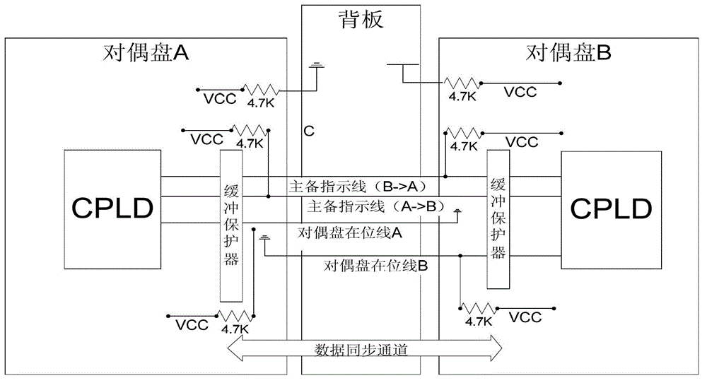
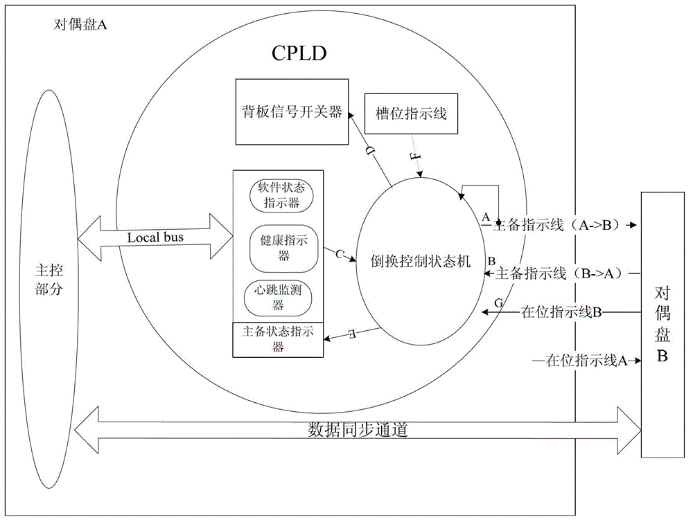
[0052] Step 1: divide the two main control disks as the main control system into a dual disk A and a dual disk B according to the main-standby redundancy protection, and the dual disk A and the dual disk B are respectively provided with a programmable logic device CPLD;

[0053] The dual disk A / B refers to the two main control disks protected by the active and standby redundancy, which one of the main control disks can be used as the dual disk A, and the corresponding other must be the dual disk B;

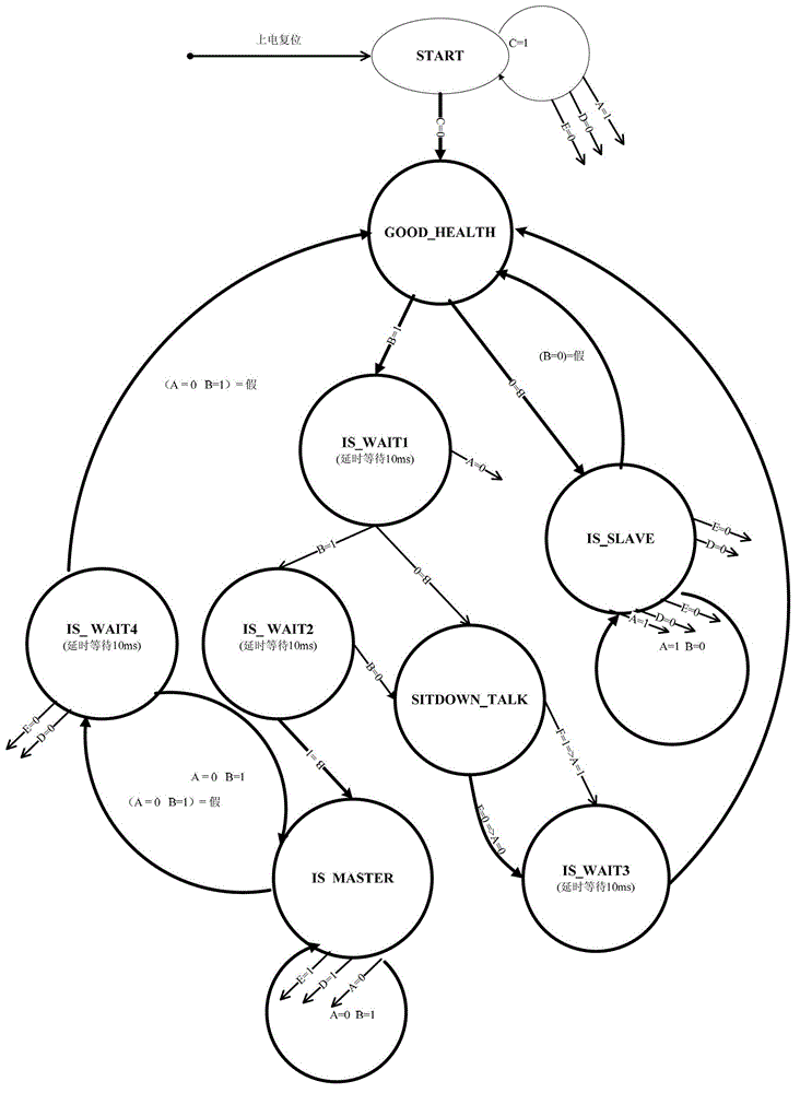
[0054] Step 2: Form an active-standby switching system, realize the following functions through digital logic circuit design, and use the hardware description language to program and compile, and downloa...


PUM


Abstract

The invention relates to a method for switching master and slave redundancy protection of a master control system of optical transmission equipment. Two master control panels are divided into a dual panel A and a dual panel B according to master and slave redundancy protection, the dual panels A and B are respectively provided with a CPLD (complex programmable logic device); a switching control module is taken as a main body for completing master and slave switching function and is realized by a digital logic circuit, the logic circuit is compiled by a related compiler by adopting a hardware description language and then is downloaded into the CPLD; in the switching method, a standard interface for a back plate and a standard interface for software are defined, logic level agreement and slot position marker line setting of the logic circuit of the switching control module are defined; and a switching process is completely realized through auto-negotiation by the logic circuit in the CPLD. By adopting the switching method disclosed by the invention, a master and slave switching mechanism is completely realized by hardware, and fussy software operation is shielded; strict double-master exclusive ability is obtained; master and slave interconnection wires are reduced, and quantity of routings on the back plate is reduced; switching speed is faster; reliability is high; and one universal module can be packaged, thus being convenient for transplantation.

Description

technical field [0001] The invention relates to the main-standby redundancy protection of the main control disk of the communication system, in particular to a switching method of the main-standby redundancy protection of the main control system of the optical transmission equipment. In particular, it refers to a switching method for active / standby redundancy protection of a main control system of an optical transmission device in an optical communication system, and the main control system refers to a main control panel. Background technique [0002] In the optical transmission equipment in the current optical communication system (abbreviated as optical communication system equipment), the functions of the control plane and the network management plane are generally integrated on a main control panel, because of its important role in the system, it must be The redundant backup of the main (main board) and one backup (standby board) makes the optical communication system ha...

Claims


Application Information

Patent Timeline
Patent Type & Authority Applications(China)
IPC IPC(8): H04J14/02H04L12/24
Inventor 李传宝陈俊强罗婷陈立超
Owner FENGHUO COMM SCI & TECH CO LTD
Learn More