
Continuous variable quantum key distribution system and synchronous realization method thereof

A quantum key distribution and implementation method technology, which is applied in the field of continuous variable quantum key distribution system, can solve the problems that continuous variable quantum key distribution cannot be applied, and achieve the effect of reducing bit error rate and overcoming interference

Active Publication Date: 2012-10-10
SHANGHAI JIAODA INTELLECTUAL PORPERTY MANAGEMENT CO LTD +1
View PDF3 Cites 77 Cited by
  • Summary
  • Abstract
  • Description
  • Claims
  • Application Information

AI Technical Summary

Problems solved by technology

[0015] But above-mentioned synchronizing device and synchronizing method can't be applicable to continuous variable quantum key distribution

Method used


Image

  • Continuous variable quantum key distribution system and synchronous realization method thereof
  • Continuous variable quantum key distribution system and synchronous realization method thereof

Examples


Embodiment 1

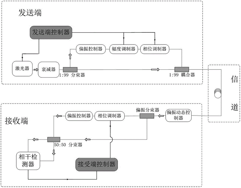
[0051] Such as figure 1 As shown, this embodiment provides a continuous variable quantum distribution system. The transmitting end includes an optical path part and a circuit control part. The optical path part is mainly composed of a laser, an attenuator, a beam splitter, a polarization controller, an amplitude controller, a phase controller, coupler etc. The circuit control part is the transmitter controller module, which is composed of a true random key generator, 2 analog voltage outputs, and 1 clock trigger. The true random key generator is to generate a true random key. The 2-way analog voltage output is used to modulate the key onto the optical pulse by controlling the amplitude modulator and phase modulator, and the 1-way clock signal is used to trigger the laser source.

[0052] The system of this embodiment uses the quasi-single photon generated by the large attenuation of the laser pulse emitted from the semiconductor laser as the information carrier—the laser ligh...

Embodiment 2

[0054] This embodiment provides a continuous variable quantum key distribution system synchronization implementation method, the specific steps are as follows:

[0055] (1) The continuous variable quantum key distribution terminal sends the character synchronization sequence frame according to the adjustment range of the polarization controller and the amplitude controller.

[0056] (2) The receiving end of the continuous variable quantum key samples the output signal of the coherent detector, and extracts the peak value of each pulse. Perform bit synchronization.

[0057] (3) On the basis of successful bit synchronization, the receiving end of the continuous variable quantum key selects the alternate data judgment threshold according to the noise fluctuation level, and starts to find the character start time. Judgment is made on the synchronization sequence frame sent by the sender. If the bit synchronization is not successful, proceed to step (2).

[0058] (4) If the char...


PUM


Abstract

The invention discloses a continuous variable quantum key distribution system and a synchronous realization method thereof. The continuous quantum key distribution system consists of a light path part and a circuit control part, wherein the light path part mainly consists of a laser, an attenuator, a beam splitter, a polarization controller, am amplitude controller, a phase controller and a coupler. A control part is a transmission end controller module and consists of a true random key generator, an analog voltage output and a trigger clock output. The synchronous method comprises a bit synchronizing step and a frame synchronizing step. The invention provides a completely novel synchronous realization scheme based on properties of continuous variable quantum in an optical fiber, the practical orientation of the continuous variable quantum key distribution system is promoted, and the interference that the continuous variable quantum on the synchronous realization in the optical communication process also can be effectively overcome.

Description

technical field [0001] The invention relates to a technology in the technical field of optical fiber communication, in particular to a continuous variable quantum key distribution system and a method for synchronizing the same. Background technique [0002] In 1999, Ralph first proposed the concept of quantum key distribution using continuous variables from an experimental point of view and analyzed its security. Continuous variable quantum key distribution has developed rapidly, and various schemes have been proposed one after another. In 2000, M. Hillery proposed a quantum key distribution scheme based on compressed states from a theoretical point of view. In 2001, D.Gottesman and J.Preskill of California Institute of Technology used the concept of continuous variable error correction codes to prove the security of their compressed state-based quantum key distribution scheme. This is the first time to prove the continuous variable quantum Security of key distribution. Fr...

Claims


Application Information

Patent Timeline
IPC IPC(8): H04L9/08H04L27/26
Inventor 申泽源肖俊俊何广强曾贵华
Owner SHANGHAI JIAODA INTELLECTUAL PORPERTY MANAGEMENT CO LTD
Learn More