Copper foil for secondary battery negative electrode power collector

A technology for negative electrode current collectors and secondary batteries, applied in the direction of electrode carriers/current collectors, battery electrodes, circuits, etc., can solve problems such as increased roughness, existence limit, and increased roughness deviation, and achieve adhesion Excellent, the effect of reducing weight and thickness deviation

Inactive Publication Date: 2012-10-10
JX NIPPON MINING & METALS CORP
View PDF7 Cites 13 Cited by
  • Summary
  • Abstract
  • Description
  • Claims
  • Application Information

AI Technical Summary

Problems solved by technology

However, when the rolled copper foil is subjected to roughening treatment using a copper sulfate plating bath, as described above, there is a problem that the roughness increases due to the influence of the accumulation of enlarged roughened particles, and the variation in the roughness increases.
[0008] Therefore, in order to improve the adhesiveness of the active material, it is desired to perform fine roughening treatment on the front and back sides of the rolled copper foil that can achieve uniformity in roughness and uniformity in weight and thickness, but there is a limit to this, and a balanced roughening treatment is required, so The current situation requires the development of copper foil for negative electrode collectors of secondary batteries

Method used


Image

  • Copper foil for secondary battery negative electrode power collector
  • Copper foil for secondary battery negative electrode power collector
  • Copper foil for secondary battery negative electrode power collector

Examples


Embodiment 1)

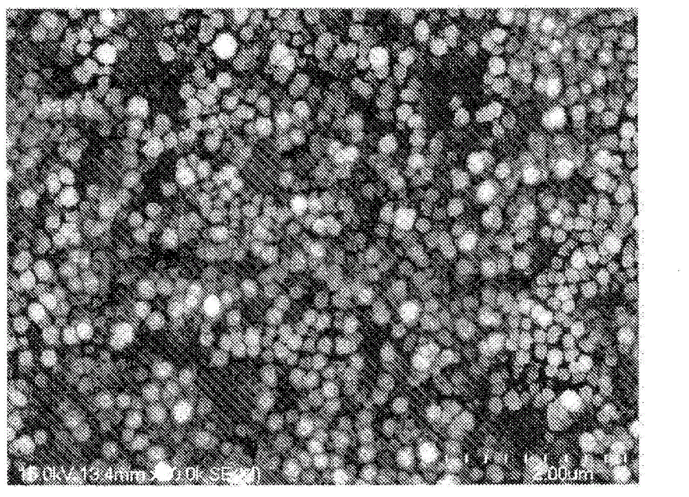
[0103] In Example 1, the average surface roughness Ra of the front and back sides measured by the laser microscope was 0.07 μm, and the three-dimensional surface area when the surface of the roughened surface was measured by the laser microscope was set as (A), and set as The two-dimensional area of ​​the projected area during the measurement of the three-dimensional surface area is (B), set (A) / (B)=(C) when the calculated value is (C), and use a laser microscope to measure the unroughened rolled copper The three-dimensional surface area of ​​the surface of the foil and copper alloy foil is (A'), and the two-dimensional area as the projected area when the three-dimensional surface area is measured is (B'), and (A') / (B')=( When the calculated value of C') is (C'), (C) / (C') is 1.004.

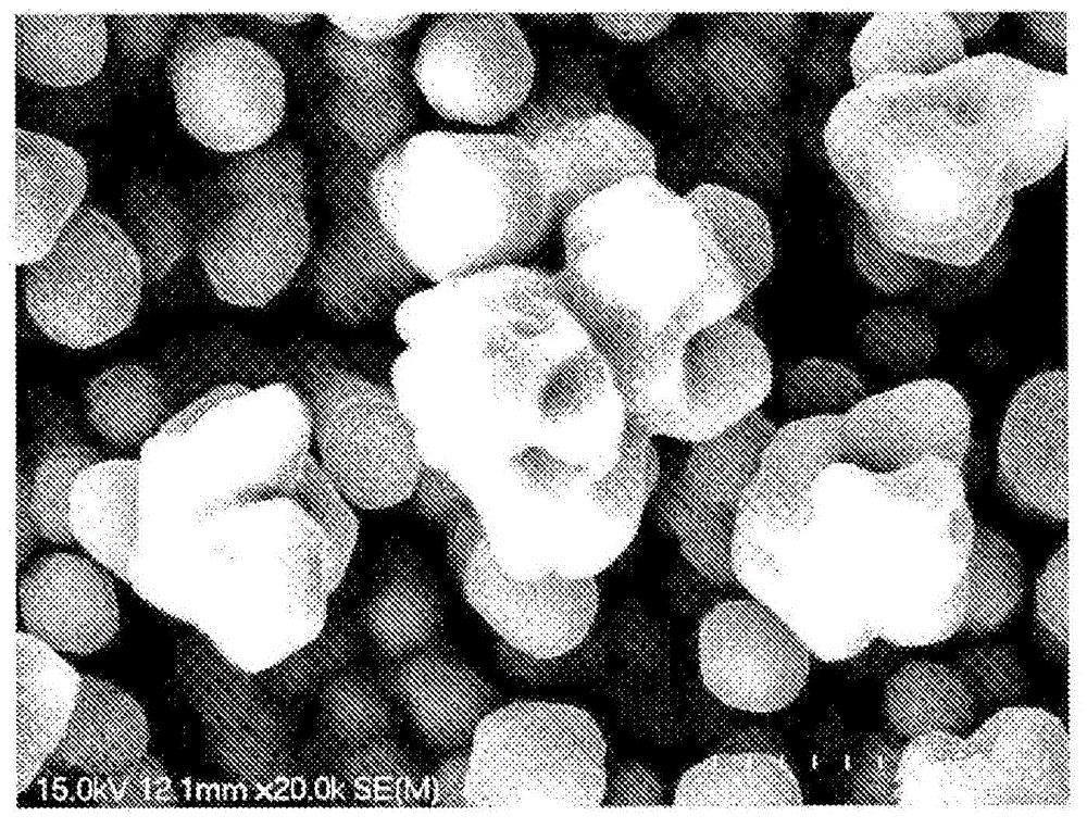
[0104] The SEM picture (20000 times) of the roughened particles at this time is like figure 1 Shown. As that figure 1 As shown, fine and uniform particles are formed. In addition, the average diame...

Embodiment 2)

[0111] In Example 2, the average surface roughness Ra of the front and back sides measured by the laser microscope was 0.07 μm, and the three-dimensional surface area when the roughened surface was measured by the laser microscope was set as (A). When the two-dimensional area of ​​the projected area when measuring the surface area is (B), set (A) / (B)=(C) when the calculated value is (C), and use a laser microscope to measure the unroughened rolled copper foil and The three-dimensional surface area of ​​the surface of the copper alloy foil is (A'), and the two-dimensional area that is the projected area when the three-dimensional surface area is measured is (B'), and (A') / (B')=(C') When the calculated value of) is (C'), (C) / (C') is 1.05.

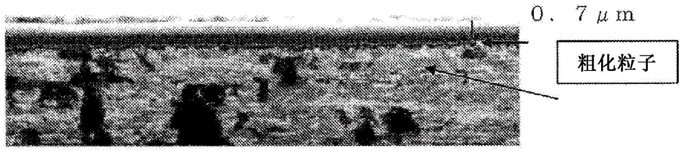
[0112] In addition, the average diameter of the roughened particles on the roughened surface is 0.1~0.4μm, and the weight thickness deviation <0.5 (σ). In addition, the maximum height of the roughening treatment layer is 0.2 μm, which is within...

Embodiment 3)

[0114] In Example 3, the average surface roughness Ra of the front and back sides measured by the laser microscope was 0.15 μm, and the three-dimensional surface area of ​​the roughened surface measured by the laser microscope was set as (A), and the three-dimensional When the two-dimensional area of ​​the projected area when measuring the surface area is (B), set (A) / (B)=(C) when the calculated value is (C), and use a laser microscope to measure the unroughened rolled copper foil and The three-dimensional surface area of ​​the surface of the copper alloy foil is (A'), and the two-dimensional area that is the projected area when the three-dimensional surface area is measured is (B'), and (A') / (B')=(C') When the calculated value of) is (C'), (C) / (C') is 1.03.

[0115] In addition, the average diameter of the roughened particles on the roughened surface is 0.1~0.4μm, and the weight thickness deviation <0.5 (σ). In addition, the maximum height of the roughening treatment layer is 0...


PUM

PropertyMeasurementUnit
diameteraaaaaaaaaa
heightaaaaaaaaaa
surface roughnessaaaaaaaaaa

Abstract

Provided is a copper foil for a secondary battery negative electrode power collector, which is obtained by performing a roughing process on both of the front and back surfaces of a rolled copper alloy foil. The copper foil is characterized in that, in the case where an average surface roughness Ra of the front and back surfaces which is measured by a laser microscope is 0.04 to 0.20 [mu]m, and a calculation value (C) is obtained from (A) / (B) = (C) in which (A) represents a three-dimensional surface area that is obtained by measuring the surface of the roughed surface by the laser microscope, and (B) represents a two-dimensional area, which is a projection area at the time of the measurement of the three-dimensional surface area, and in the case where a calculation value (C') is obtained from (A') / (B') = (C') in which (A'); represents a three-dimensional surface area that is obtained by measuring the surface of a rolled copper foil and a copper alloy foil which are not subjected to the roughing process by the laser microscope, and (B') represents a two-dimensional area, which is a projection area at the time of the measurement of the three-dimensional surface area, 1.0 < (C) / (C') < 1.1 is satisfied. The copper foil for a secondary battery negative electrode power collector is excellent in adhesion of secondary battery active materials, is capable of reducing the variation of weight thicknesses of the secondary battery active materials, and is also excellent in weather resistance and heat resistance.

Description

Technical field [0001] The present invention relates to a copper foil for a negative electrode current collector of a secondary battery, and particularly provides a negative electrode current collector for a secondary battery that has excellent adhesion of the active material of the secondary battery and can reduce the deviation of the weight and thickness of the active material of the secondary battery Copper foil. Background technique [0002] Copper and copper alloy foils (hereinafter referred to as copper foils) have greatly contributed to the development of electrical and electronic related industries, and have become indispensable as printed circuit materials and secondary battery negative current collectors. Copper foil is required to have high adhesion to a resin substrate or other materials. For example, in the case of a negative electrode current collector for a lithium secondary battery, the adhesion between the copper foil and the negative electrode active material is...

Claims


Application Information

Patent Timeline
Patent Type & Authority Applications(China)
IPC IPC(8): H01M4/66C25D5/10C25D7/06C25D9/08
CPCY02E60/12H01M4/661C25D9/04C25D5/34C25D5/10C25D5/48H01M2004/021C25D3/58C25D3/562C25D3/565Y10T29/49108Y02E60/10C25D5/611C25D7/06C25D9/08
Inventor 新井英太神永贤吾三木敦史岩崎友一
Owner JX NIPPON MINING & METALS CORP
Why Eureka
Try Eureka