
The fuel cell

A fuel cell and electrolyte membrane technology, which is used in fuel cells, fuel cell components, and transportation fuel cell technology to achieve the effect of suppressing the reduction of power generation efficiency and preventing power generation from stopping.

Active Publication Date: 2015-08-05
TOYOTA SHATAI KK
View PDF5 Cites 0 Cited by
  • Summary
  • Abstract
  • Description
  • Claims
  • Application Information

AI Technical Summary

Problems solved by technology

Therefore the following problem arises

Method used


Image

  • The fuel cell
  • The fuel cell
  • The fuel cell

Examples


Embodiment Construction

[0039] (first embodiment)

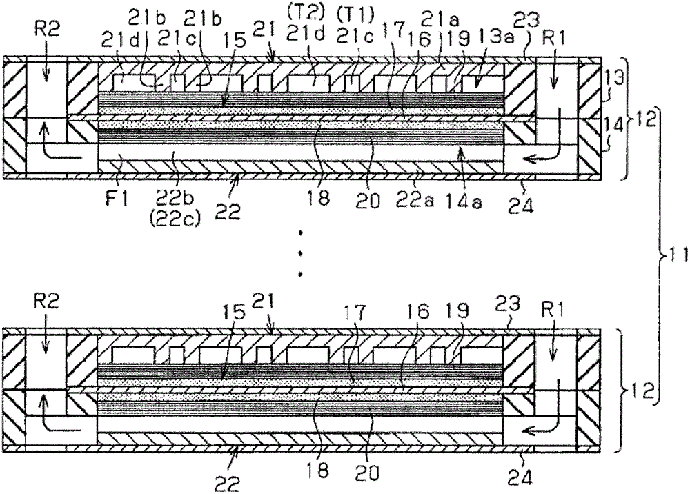
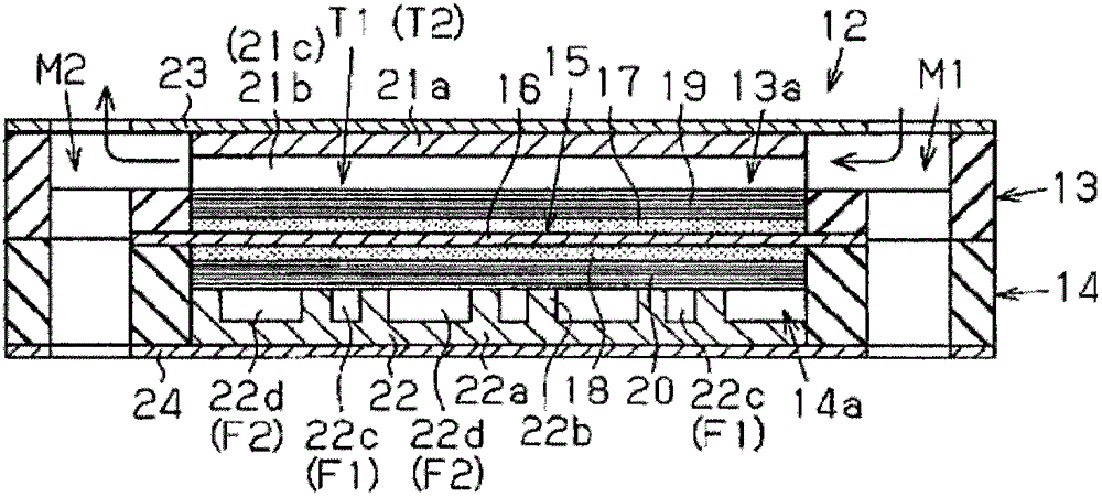
[0040] refer to Figures 1 to 4 and 13 describe the fuel cell according to the first embodiment of the present invention.

[0041] Such as Figure 13 As shown, the fuel cell stack 11 of the first embodiment is a solid polymer electrode electrolyte fuel cell, and includes a plurality of stacked power generation cells 12 .

[0042] Such as figure 1 As shown, these power generation cells 12 each include square first and second frames 13 , 14 , and a membrane electrode assembly (MEA) 15 as an electrode structure positioned within the first and second frames 13 , 14 . The first and second frames 13, 14 are made of synthetic resin such as synthetic rubber. A passage space 13 a for fuel gas is formed in the first frame 13 , and a passage space 14 a for oxidizing gas is formed in the second frame 14 . The membrane electrode assembly 15 is positioned between the first and second frames 13 , 14 .

[0043] Such as figure 1 and 2 As shown, each power g...


PUM


Abstract

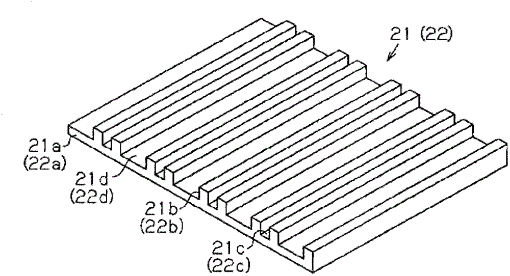
A membrane electrode assembly (15) formed by a solid electrolyte membrane (16) and electrode catalyst layers (17, 18) is interposed between a pair of frames (13, 14). Gas diffusion layers (19, 20) are laminated onto the surface of the electrode catalyst layers (17, 18). A first gas passage forming member (21) is laminated onto the surface of the gas diffusion layer (19) while a second gas passage forming member (22) is laminated onto the surface of the gas diffusion layer (20). Separators (23, 24) contact surfaces of the frame (13, 14) and the first and second gas passage forming member (21, 22). A plurality of first and second straight grooves (21c, 21d) are formed on the first gas passage forming member (21), such that the widths (w1, w2) differ from each other, and cross-sectional areas of the paths for the first and second gas passages (T1, T2) differ from each other.

Description

technical field [0001] The present invention relates to a fuel cell for use in an electric vehicle or the like, and more particularly to a fuel cell capable of improving power generation performance. technical background [0002] Typically, a fuel cell consists of components such as Figure 13 A fuel cell stack 11 is formed by stacking a plurality of power generation cells 12 as shown in FIG. like Figure 14 As shown, an electrode assembly 15 is placed at a coupling portion of a pair of frames 13, 14 for forming these power generation cells 12, respectively. The electrode assembly 15 includes a solid electrolyte membrane 16, an electrode catalyst layer 17 positioned on the anode side, and an electrode catalyst layer 18 positioned on the cathode side. The outer peripheral edge of the solid electrolyte membrane 16 is fixed by being sandwiched between the frames 13, 14. The anode side gas diffusion layer 19 is laminated on the surface of the electrode catalyst 17 , and the c...

Claims


Application Information

Patent Timeline
Patent Type & Authority Patents(China)
IPC IPC(8): H01M8/02H01M8/10
CPCY02T90/32Y02E60/50H01M2008/1095H01M8/0263H01M8/0265H01M2250/20H01M8/026Y02T90/40
Inventor 川尻浩右桥本圭二二见谕林友和
Owner TOYOTA SHATAI KK
Learn More