Automatic magnetic grinding machine

A magnetic grinding, fully automatic technology, used in grinding machines, machine tools suitable for grinding workpiece edges, and surface polishing machine tools, etc., can solve problems such as reduced production efficiency, low grinding efficiency, and inability to streamline production, and improve processing efficiency. , The effect of guaranteeing the processing quality and saving manpower and material resources

Active Publication Date: 2016-12-21
罗泽波
View PDF6 Cites 2 Cited by
  • Summary
  • Abstract
  • Description
  • Claims
  • Application Information

AI Technical Summary

Problems solved by technology

[0002] The magnetic grinding machine uses a magnetic field force to conduct abrasive materials (such as: stainless steel needles), so that the abrasive materials perform high-frequency rotational flow, vibration, reversing and tumbling, rubbing against the surface of the workpiece, and rubbing on the inner hole, inner and outer teeth, and surface or concave-convex surface of the workpiece. , to achieve cleaning, degreasing impurities, deburring, grinding and other precision polishing effects; at present, most of the current magnetic grinding machines are one-to-one processing methods, and a motor drives a disk to grind the workpiece in a single grinding container. The efficiency is low, and it cannot meet the needs of large-volume workpiece processing. In addition, the waste after grinding is easily attached to the workpiece because it stays in the grinding container, and the workpiece needs to be cleaned afterwards, which increases manpower and material resources, and cannot be produced in an assembly line, reducing production. efficiency

Method used


Image

  • Automatic magnetic grinding machine
  • Automatic magnetic grinding machine
  • Automatic magnetic grinding machine

Examples


Embodiment Construction

[0024] The present invention will be further described below in conjunction with the accompanying drawings of the description.

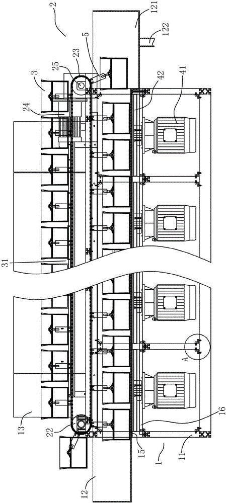
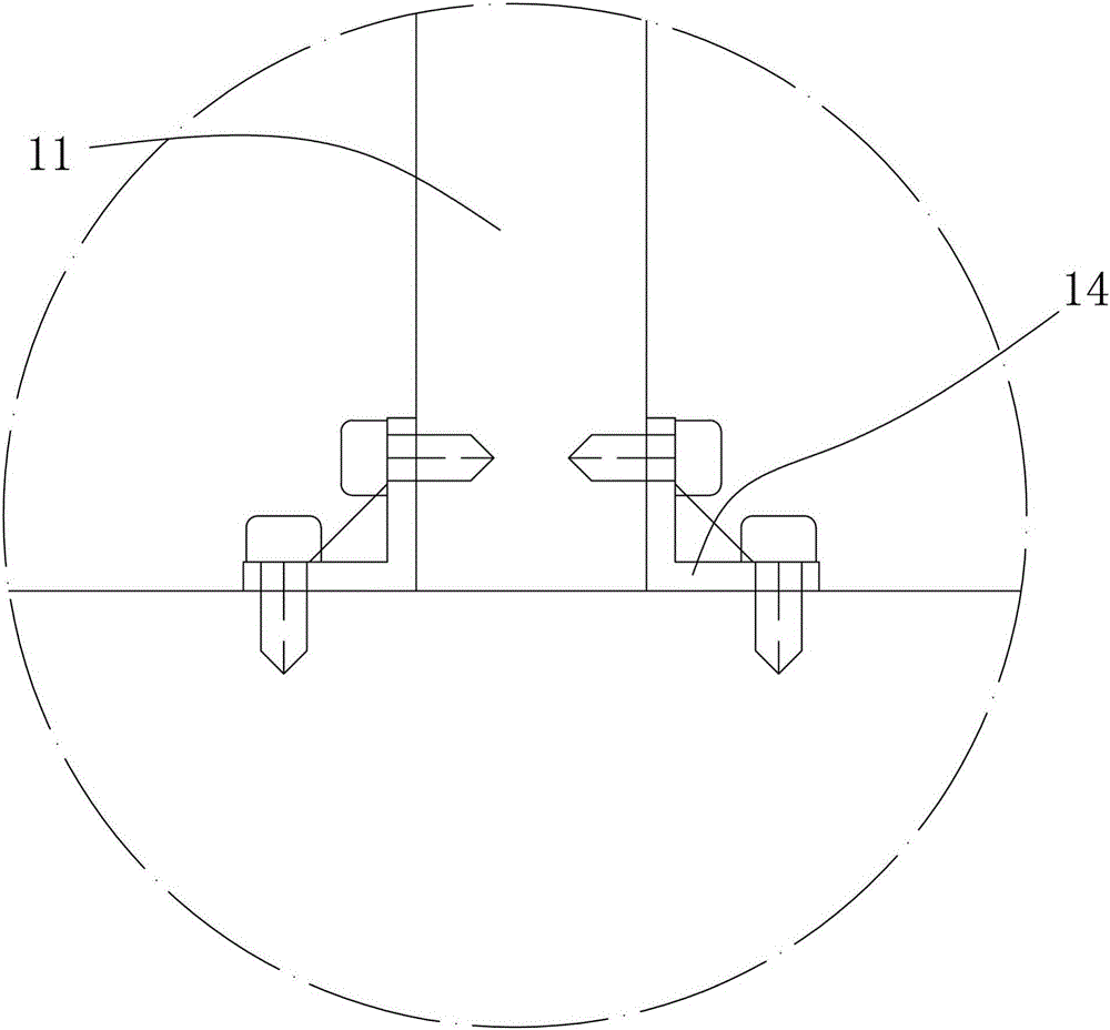
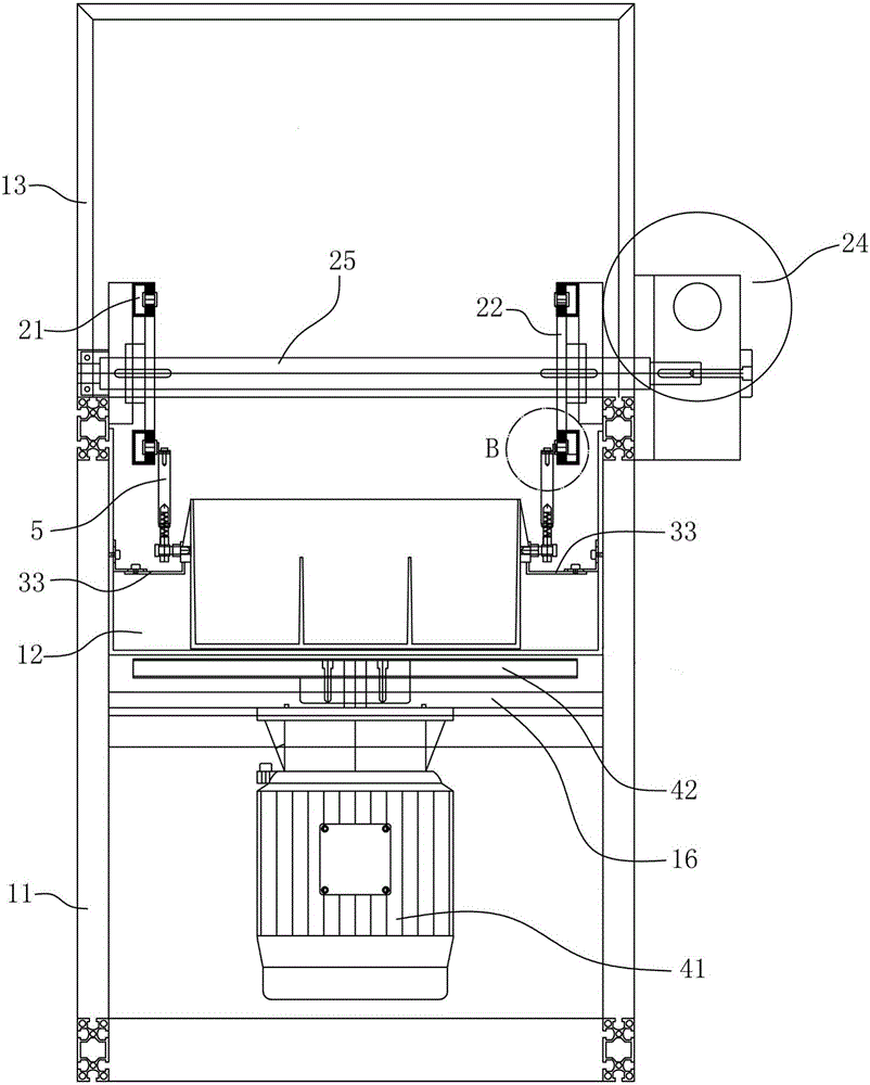
[0025] Such as Figure 1-8 As shown, the present invention relates to a fully automatic magnetic grinding machine, which includes a body 1, a transmission mechanism 2 for cyclic transmission, a plurality of grinding containers 3 for containing materials, and a magnetic force generating device 4 for grinding. The body 1 includes The frame 11, the water tank 12 installed on the frame 11, the protective plate installed on the frame 11 and the machine cover 13 arranged on the upper end of the frame 11, the frame 11 is made of a plurality of aluminum profiles through right-angled connectors 14 are connected end to end and fixed with screws. The aluminum profiles forming the frame 11 can be 4×4 and 4×8 (in cm) thickened general standard aluminum profiles, and the two sides and the top of the frame 11 are made of iron. The plate is used as a protective pla...


PUM


Abstract

The invention relates to the technical field of grinding and polishing equipment and discloses a full-automatic magnetic force grinder. The full-automatic magnetic force grinder comprises a grinder body, a transmission mechanism for circular transmission, a plurality of grinding containers for containing materials and a magnetic force generating device for grinding, wherein the transmission mechanism is arranged at the upper end of the grinder body; the grinding containers are connected to the transmission mechanism through a movable bracket to form an assembly line structure in circular transmission; and the magnetic force generating device is arranged below the grinding containers and is arranged at the lower end of the grinder body through a fixing plate. During operation, according to the transmission mechanism in circular transmission, the grinding containers uninterruptedly pass through a high-speed rotating powerful magnetic disc at a low speed, so that abrasive materials such as stainless steel needles in the grinding containers rotate, flow, vibrate, reverse and turn at high frequency, and the surface of the workpiece is rubbed so that grinding and polishing treatment on the workpiece is achieved; and moreover, uninterrupted assembly line type production is realized, the machining efficiency is improved, the machining quality is guaranteed, and manpower and material resources are saved.

Description

technical field [0001] The invention relates to the technical field of grinding and polishing equipment, in particular to a fully automatic magnetic grinding machine in which a plurality of grinding containers are driven by a cyclic transmission mechanism to form an uninterrupted assembly line production operation on a high-speed rotating magnetic force generating device. Background technique [0002] The magnetic grinding machine uses a magnetic field force to conduct abrasive materials (such as: stainless steel needles), so that the abrasive materials perform high-frequency rotational flow, vibration, reversing and tumbling, rubbing against the surface of the workpiece, and rubbing on the inner hole, inner and outer teeth, and surface or concave-convex surface of the workpiece. , to achieve cleaning, degreasing impurities, deburring, grinding and other precision polishing effects; at present, most of the current magnetic grinding machines are one-to-one processing methods, ...

Claims


Application Information

Patent Timeline
Patent Type & Authority Patents(China)
IPC IPC(8): B24B31/10B24B31/14B24B31/12B24B57/02
Inventor 罗泽波
Owner 罗泽波
Why Eureka
Try Eureka