Rolling bearing

A technology of rolling bearings and rolling elements, applied in the direction of bearings, bearing components, shafts and bearings, which can solve problems such as complex working steps and post-processing steps

Active Publication Date: 2012-10-17
SCHAEFFLER TECH AG & CO KG
View PDF8 Cites 1 Cited by
  • Summary
  • Abstract
  • Description
  • Claims
  • Application Information

AI Technical Summary

Problems solved by technology

This means that complex work steps and post-processing steps are required

Method used


Image

  • Rolling bearing

Examples


Embodiment Construction

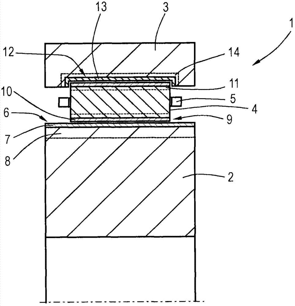
[0027] A cross-sectional view of a rolling bearing 1 according to the invention is shown as an example in the drawing. The rolling bearing 1 is composed of an inner ring 2 , an outer ring 3 and rolling elements 4 arranged between the inner ring 2 and the outer ring 3 , the rolling elements 4 being held in a cage 5 .

[0028] The inner ring 2 has an outer raceway 6 on which a polishing layer 7 is arranged. An edge region 8 is formed below the polishing layer 7 , in which an increased nitrogen and carbon content is given by the carbonitriding method. The nitrogen content is between 0.03-0.8%, wherein at least 0.02% of the nitrogen is dissolved in the steel substrate. In addition, the steel substrate contains a small nickel component of ≤0.4%, a silicon content of 0.2%-1.0%, a chromium content of ≥1.0%, a sulfur content of ≤0.008%, an oxygen content of ≤15ppm and an oxygen content of ≤50ppm Titanium content.

[0029] The surfaces 9 of the rolling bodies are also provided with ...


PUM

PropertyMeasurementUnit
thicknessaaaaaaaaaa
hardnessaaaaaaaaaa
hardnessaaaaaaaaaa

Abstract

The present invention relates to a rolling bearing, comprising an outer ring, an inner ring and a rolling body rolling on a rolling way between the outer ring and the inner ring, wherein the rolling way of the inner ring and / or the outer ring and / or the surface of the rolling body are / is provided with a polishing layer, the inner ring and / or the outer ring and / or the rolling body are / is prepared by steel, the steel is provided with a hardness of 58 HRC at least below the polishing layer, and at least below the polishing layer there are provided 0.03-0.08% nitrogen at least in an edge layer, wherein the nitrogen is at least partially dissolved; 0.1-1.2% carbon; nickel not more than 0.4%; 0.2-1.0% silicon; chrome not smaller than 1.0%; sulphur not more than 0.008%; oxygen not more than 15 ppm; and titanium not more than 50 ppm.

Description

technical field [0001] The invention relates to a rolling bearing, which comprises an outer ring, an inner ring and rolling bodies rolling on the raceways of the outer ring and the inner ring. Background technique [0002] Rolling bearings are often subjected to other loads in addition to the Hertzian pressure due to the inherent rolling operation, for example superimposed vibration loads due to vibrations or high temperatures or temperature changes, such vibration loads are caused, for example, by friction or fluctuating ambient temperatures or electric fields, For example, due to the operation of the frequency converter. Typical application examples are transmission bearings in wind turbines or in screw compressors, etc. Compared with the average service life on which the rolling bearings are designed, it is often noted in this case that the bearing failure is significantly earlier, although the Hertzian surface pressure is very clearly below the endurance strength. Thes...

Claims


Application Information

Patent Timeline
Patent Type & Authority Applications(China)
IPC IPC(8): F16C33/62F16C33/34
CPCF16C33/64F16C33/34F16C2240/18F16C33/62F16C2204/60
Inventor 维尔纳·特罗扬沃尔特·霍尔韦格西尔克·勒施
Owner SCHAEFFLER TECH AG & CO KG
Why Eureka
Try Eureka