
A welding method for suppressing cracks in aluminum alloy t-joints

A welding method, aluminum alloy technology, applied in welding equipment, welding accessories, manufacturing tools, etc., to release internal stress, avoid repeated softening, and suppress cracks

Active Publication Date: 2022-07-05
HARBIN INST OF TECH
View PDF13 Cites 0 Cited by
  • Summary
  • Abstract
  • Description
  • Claims
  • Application Information

AI Technical Summary

Problems solved by technology

[0004] The present invention aims at the problem of thermal cracks existing in double-sided laser welding of aluminum alloy T-joints, and proposes a welding method for suppressing cracks in aluminum alloy T-joints

Method used


Image

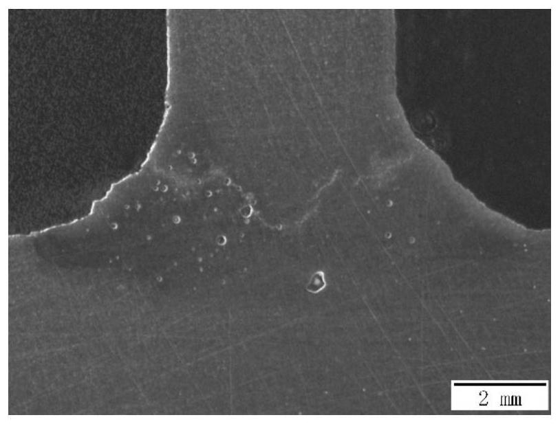
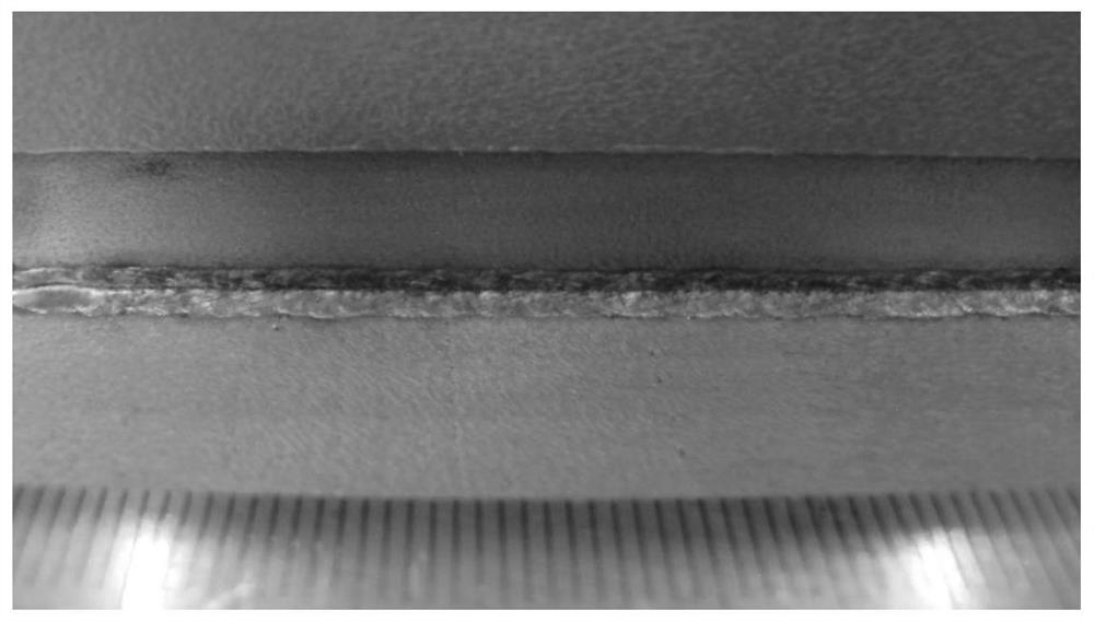
  • A welding method for suppressing cracks in aluminum alloy t-joints
  • A welding method for suppressing cracks in aluminum alloy t-joints
  • A welding method for suppressing cracks in aluminum alloy t-joints

Examples


Embodiment 1

[0039] The method of welding 2195 aluminum-lithium alloy 4mm stringer and 6mm skin T-joint in this embodiment is as follows:

[0040] Step 1: the parts to be welded of the workpiece are processed to the required precision as required, and the two side surfaces after the workpiece are processed are polished or cleaned;

[0041] Step 2: fix the workpiece to be welded after grinding or cleaning on the welding fixture, the stringer is perpendicular to the surface of the skin, the upper preload is not less than 50N, the inclination angle α of the welding wire 1 is 20°, and the inclination angle β of the laser is 52°, The inclination angle γ of the welding torch is 35°, and the inclination angle θ of the composite welding head is 32°.

[0042] Step 3: The same parameters are used on both sides, the laser defocus amount is ﹢3mm, the laser power is 5000W, the welding speed is 5m / min, the wire feeding speed is 180mm / min, the filament spacing is 5mm, the arc current is 85A, and the arc ...

Embodiment 2

[0046] The method of welding 2195 aluminum-lithium alloy 4mm stringer and 6mm skin T-joint in this embodiment is as follows:

[0047] Step 1: the parts to be welded of the workpiece are processed to the required precision as required, and the two side surfaces after the workpiece are processed are polished or cleaned;

[0048] Step 2: fix the workpiece to be welded after grinding or cleaning on the welding fixture, the row bar is perpendicular to the surface of the skin, the upper preload is not less than 50N, the inclination angle α of the welding wire 1 is 20°, and the inclination angle β of the laser is 52°, The inclination angle γ of the welding torch is 35°, and the inclination angle θ of the composite welding head is 32°.

[0049] Step 3: use the same parameters on both sides, the laser defocus amount is ﹢3mm, the laser power is 5000W, the welding speed is 5m / min, the wire feeding speed is 180mm / min, the distance between the filaments is 2mm, the arc current is 85A, and ...


PUM

PropertyMeasurementUnit
angleaaaaaaaaaa

Abstract

A welding method for suppressing cracks in an aluminum alloy T-shaped joint relates to the field of welding. The invention aims to solve the problem of thermal cracks existing in the double-sided laser welding of the aluminum alloy T-joint. The present invention mainly utilizes the composition of the welding wire 1 to enhance the internal consistency of the welding seam and improve the strength of the welding seam, and uses the composition of the welding wire 2 to suppress cracks at the front of the solidification of the rear molten pool. On the premise of ensuring the overall flow trend of the molten pool, the invention can further improve the elimination of pores and the reduction of heat input by using heat sources such as swing laser and pulse / AC CMT. The invention is applied to the field of manufacturing welding.

Description

technical field [0001] The invention belongs to the field of material processing engineering, and in particular relates to a welding method for suppressing cracks in an aluminum alloy T-shaped joint. Background technique [0002] In the manufacturing industries of aircraft, automobiles and rolling stock, in order to reduce the self-weight of the vehicle and improve the carrying capacity, more and more light metal alloys and thin-walled lightweight structures are used. Light alloys based on titanium alloys and aluminum alloys have been widely used in the manufacture of structural parts in aerospace and other fields to meet the development needs of modern aircraft for lightweight and high performance of key structural parts. In the manufacturing process of aerospace light alloy thin-walled structural parts, the connection between the wall plate and the stringer is usually involved. After the traditional riveting process is replaced by welding, the weight reduction effect is re...

Claims


Application Information

Patent Timeline
Patent Type & Authority Patents(China)
IPC IPC(8): B23K9/067B23K9/133B23K9/235B23K9/28B23K9/32
CPCB23K9/067B23K9/133B23K9/235B23K9/287B23K9/32
Inventor 雷正龙黎炳蔚夏佩云胡蓝尹玉环张新瑞陈彦宾
Owner HARBIN INST OF TECH
Learn More