Inflation tool device of absorber

A shock absorber and tooling technology, which is applied in the container filling method, the container discharge method, and the equipment loaded into the pressure vessel, etc., can solve the problems of slow push rod speed, low work efficiency and low reliability of hydraulic equipment. , to achieve the effect of good sealing, convenient operation and strong versatility

Active Publication Date: 2012-10-17
LIUZHOU CARRERA SHOCK ABSORBER CO LTD
View PDF7 Cites 2 Cited by
  • Summary
  • Abstract
  • Description
  • Claims
  • Application Information

AI Technical Summary

Problems solved by technology

[0003] 1. The hydraulic equipment pushes the ejector rod at a slow speed, and the work efficiency is not high. The descending stroke of the ejector rod is determined by the oper

Method used


Image

  • Inflation tool device of absorber
  • Inflation tool device of absorber
  • Inflation tool device of absorber

Examples


Embodiment

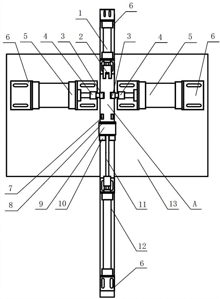
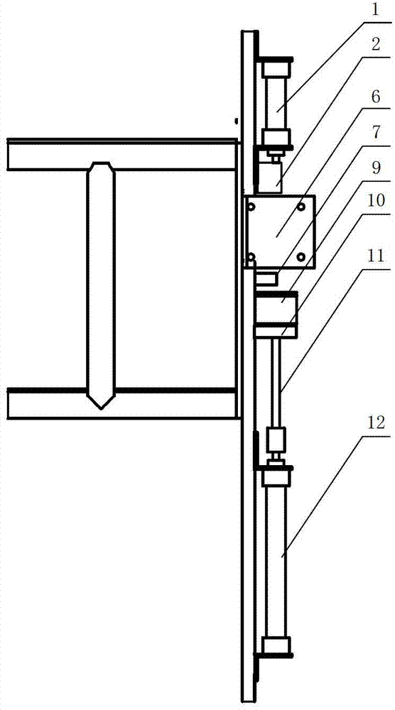
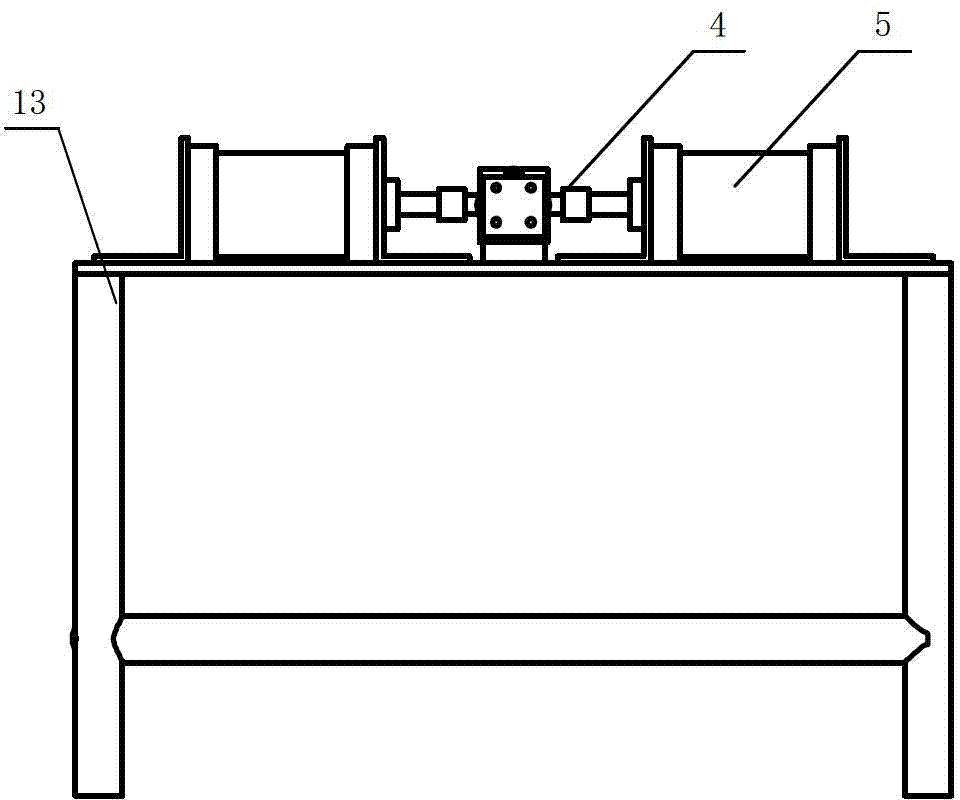
[0030] A shock absorber inflation tooling device, including an electrical control system, a positioning mechanism installed on a tooling platform 13, an inflation mechanism and a pressure point mechanism, the positioning mechanism is used to fix the shock absorber cylinder 14, including a positioning cylinder 1, The pressing base block 2, the cylinder positioning block 3 and the cylinder positioning V-shaped block 7, the pressing base block 2, the cylinder positioning block 3 and the cylinder positioning V-shaped block 7 are respectively located at the front of the pneumatic cylinder station, In the middle and the tail, the positioning cylinder 1 is installed on the front end of the pressing base block 2 through the cylinder fixing block 6 and is on the same central axis as the pneumatic cylinder tube station, and the piston end of the positioning cylinder 1 is connected with the pressing base block 2.

[0031] The inflation mechanism is used to press the floating piston into t...


PUM


Abstract

The invention discloses an inflation tool device of an absorber. The inflation tool device comprises an electrical control system, a positioning mechanism, an inflation mechanism and a pressure point mechanism, wherein the positioning mechanism comprises positioning air cylinders which are respectively arranged the front part, middle part and the tail part of a cylinder tube station to be inflated, a pressing base block, a cylinder tube locating block and a cylinder tube positioning V-shaped block; the positioning air cylinder is connected with the pressing base block, the inflation mechanismcomprises an inflation module, an inflation module fixed block, an ejector rod and an inflation air cylinder which are sequentially arranged on the rear part of the cylinder tube station to be inflated; one end of the ejector rod is connected with the inflation air cylinder, the other end of the ejector rod passes through the centre of the inflation module, the pressure point mechanism comprises left and right pressure point air cylinders arranged on the two sides of the cylinder tube station to be inflated, and a pressure head connected with the left and right pressure point air cylinders right faces to spacing depression points to be processed on a cylinder tube; all the air cylinders are controlled by the electrical control system. The inflation tool device has the advantages of good air tightness, convenience and simplicity in operation, high production efficiency and strong applicability; and due to the adoption of a circuit for controlling, the inflation tool device has good inflation effect and can generate great pressure, so that the absorber has stable inflation quality..

Description

technical field [0001] The invention relates to a shock absorber tooling device, in particular to a shock absorber inflation tooling device. Background technique [0002] During the assembly process of the shock absorber, it is necessary to press the floating piston into the cylinder and inflate the cylinder at the same time. Dimple for piston stop. At present, there is no special inflatable tooling equipment. Usually, the hydraulic equipment is used to press the floating piston into the cylinder through the ejector rod, and after reaching the set position, the limit concave point is manually punched. The problem is: [0003] 1. The hydraulic equipment pushes the ejector rod at a slow speed, and the work efficiency is not high. The descending stroke of the ejector rod is determined by the operator's visual judgment, with poor precision and low reliability; [0004] 2. It is not only inefficient but also labor-intensive to manually punch the limiting recesses. Contents...

Claims


Application Information

Patent Timeline
IPC IPC(8): F17C5/06F17C13/00
Inventor 赵俊发容家坤廖嵘
Owner LIUZHOU CARRERA SHOCK ABSORBER CO LTD
Why Eureka
Try Eureka