Super-resolution microscopic imaging method and system based on microcantilever and microsphere combined probe

A combined probe and microscopic imaging technology, which is applied in scanning probe microscopy, scanning probe technology, measuring devices, etc., can solve the problems of small imaging magnification, uncontrollable spreading area, and difficulty in practical application

Inactive Publication Date: 2012-10-17
ZHEJIANG UNIV
View PDF7 Cites 27 Cited by
  • Summary
  • Abstract
  • Description
  • Claims
  • Application Information

AI Technical Summary

Problems solved by technology

However, this technique still has obvious limitations in at least several aspects: First, in principle, the microspheres are spread on the surface of the observed sample, and the longitudinal distance between the lower end surface of the microspheres and the sample surface is zero, that is, the sample is located at At a longer distance within the focus of the microsphere, obviously, the imaging magnification of the microsphere lens at this time is smaller, because within the focus range, the closer the sample is to the focus, the greater the magnification. Therefore, in order to obtain a higher magnification and resolution, it is necessary to lift the microspheres a certain distance away from the sample surface, instead of spreading the microspheres on the sample surface; secondly, in terms of method, the existing microsphere sowing method is random, and it is completely impossible to control the area where it is sown. That is, the sample area of ​​interest cannot be consciously and effectively microscopically observed, but the sample surface area sprinkled with microspheres can only be randomly observed, so the prior art method is difficult to be practical; in addition, although the microsphere itself It is spherical, but due to its small diameter (2~10um), it is still relatively sharp. Therefore, when the microspheres are just randomly scattered on the surface of the sample, it will inevitably cause damage to the surface of the sample. Microspheres are difficult to clean up and can also contaminate samples

Method used


Image

  • Super-resolution microscopic imaging method and system based on microcantilever and microsphere combined probe
  • Super-resolution microscopic imaging method and system based on microcantilever and microsphere combined probe
  • Super-resolution microscopic imaging method and system based on microcantilever and microsphere combined probe

Examples


Embodiment Construction

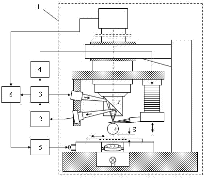
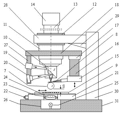
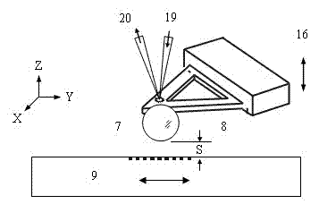
[0017] The super-resolution microscopy imaging method based on the microcantilever and microsphere combined probe is: the method of using the microcantilever and microsphere combined probe to lift the microsphere off the sample surface and the micro-nano feedback control method based on atomic force, and the introduction of atomic force microscope (AFM) microcantilever, to prepare a microcantilever-microsphere probe, which lifts the microsphere away from the surface of the sample and at the same time very close to the sample surface; introduces lasers, semi-transparent and semi-reflective prisms, position detectors and piezoelectric ceramics, etc., through micro-nano Feedback control controls the distance between the microsphere and the sample in the near-field range, breaks through the optical diffraction limit of 200nm, and realizes super-resolution optical microscopy imaging of the sample; cooperates with the stepping mobile stage to realize the lateral adjustment between the...


PUM


Abstract

The invention discloses a super-resolution microscopic imaging method and a super-resolution microscopic imaging system based on a microcantilever and microsphere combined probe. The system comprises a super-resolution microscopic imaging device which comprises the microcantilever and microsphere combined probe, piezoelectric ceramic, a laser, a transflective prism, a position sensitive element, a stepping movable table, an objective, a charge coupled device (CCD) and the like, and a control system which comprises a current-to-voltage converter, a feedback control module, a high-voltage amplifier, a stepping controller, a computer, an interface and the like. A microsphere is lifted off by the microcantilever and microsphere combined probe and is approximate to the surface of a sample, and an atomic-force-based micro/nano feedback control method is adopted, so that the distance between the microsphere and the sample is controlled in a near-field range, and super-resolution optical microscopic imaging is realized. The new super-resolution microscopic imaging method based on the microcantilever and microsphere probe has the advantages that the multi-zone, full-field and super-resolution optical microscopic imaging of the sample is realized, the limit of optical diffraction is broken, and the defects of the traditional microsphere microscopic imaging technology in many aspects are overcome.

Description

technical field [0001] The invention relates to a super-resolution microscopic imaging method and system based on a combined probe of a microcantilever and a microsphere. Background technique [0002] Since Leeuwenhoek invented the first optical microscope in 1764, the optical microscope has been the most widely used microscopic imaging tool with the largest number of applications. In 1874, Abbe proposed that the optical diffraction limit of the microscope is about 200nm, that is, the highest resolution of the optical microscope can only be about 200nm. To overcome this diffraction limit, a range of other types of microscopy techniques have been invented, including transmission electron microscopy (TEM), scanning electron microscopy (SEM), scanning tunneling microscopy (STM), atomic force microscopy (AFM), scanning near-field optics Microscopy (SNOM), etc., and gradually developed into the scanning probe microscope (SPM) family. Although SEM, TEM, STM, AFM, and SNOM have n...

Claims


Application Information

Patent Timeline
Patent Type & Authority Applications(China)
IPC IPC(8): G01Q60/06
Inventor 章海军李甸张冬仙王淑莹
Owner ZHEJIANG UNIV
Why Eureka
Try Eureka