Optical fiber fault location device and location method based on chaotic visible laser

A fiber optic fault and positioning device technology, applied in the direction of measuring devices, optical instrument testing, machine/structural component testing, etc., can solve problems such as the difficulty of determining the location of the fault point, simplify the measuring device, avoid damage to the optical fiber, and save testing costs Effect

Active Publication Date: 2016-06-08
TAIYUAN UNIV OF TECH
View PDF5 Cites 2 Cited by
  • Summary
  • Abstract
  • Description
  • Claims
  • Application Information

AI Technical Summary

Problems solved by technology

[0003] Based on the above prior art, the present invention solves the problem that the location of the fault point is difficult to determine due to the discrepancy between the length measurement and location caused by the laying and bending of the optical fiber and the actual location of the fault point, and provides a method based on chaos and visible Laser fiber optic fault location device and location method thereof

Method used


Image

  • Optical fiber fault location device and location method based on chaotic visible laser
  • Optical fiber fault location device and location method based on chaotic visible laser
  • Optical fiber fault location device and location method based on chaotic visible laser

Examples


Embodiment 2

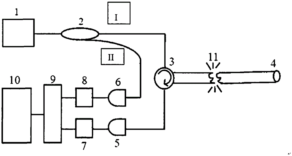
[0025]Implementation of the present invention is a positioning method for the optical fiber fault location device based on chaotic visible laser in Embodiment 1: the chaotic visible light signal is divided into detection signal I and reference signal II through fiber coupler 2, and the reference signal and the optical fiber fault point 11 reflect The final echo signal enters the signal processing device 9 for cross-correlation processing, and the principle of cross-correlation processing to realize the measurement of the propagation time of light in the optical fiber is: assuming that the chaotic laser produced by the chaotic visible laser generating device meets the characteristics of the non-periodic function f(t) , the chaotic light I and chaotic light II divided by the fiber coupler meet the characteristics of the functions k*f(t) and (1-k)f(t) respectively, and the chaotic light I as the detection light is reflected by the fiber fault point The light satisfies the function...


PUM


Abstract

The invention discloses a chaotic visible laser-based optical fiber fault positioning device and a positioning method thereof. The positioning device comprises a chaotic visible laser emitting device, an optical fiber coupler, an optical circulator, a photoelectric detector, an A / D (Analog / Digital) converter, a signal processing device and a display device. Chaotic visible laser signals emitted by the chaotic visible laser emitting device generate obvious visible bright spots at a fault point (11) of an optical fiber line to be tested (4) due to transmission, and the accurate positioning of the fault point can be realized by finding the visible bright spots in a range of the distance between a detection point and the fault point (11). According to the positioning device and the positioning method, the chaotic visible laser is used as a detection light source, and a chaos-related fault point detection technology and a visible optical fiber fault point detection technology are integrated, so that the fast and accurate detection and positioning of the optical fiber fault point is realized, and the problem that the optical fiber fault point is easily measured and not easily positioned is solved.

Description

technical field [0001] The invention relates to a laser distance measuring device and a distance measuring method thereof, in particular to a visual high-precision optical fiber fault location device and a location method thereof based on chaotic visible laser. Background technique [0002] With the wide application of optical fiber in the field of communication and sensing, optical fiber fault detection device has become an indispensable tool in optical fiber construction detection and fault maintenance. At present, commonly used optical fiber fault detection technologies include: red light optical fiber fault detection technology [CN201269801] and optical time domain reflection technology [CN1681227]. Among them, the red light optical fiber fault detection technology makes full use of the visible characteristics of red light, and realizes the precise positioning of the optical fiber fault point by generating visible bright spots through the transmission of red light at the...

Claims


Application Information

Patent Timeline
Patent Type & Authority Patents(China)
IPC IPC(8): H04B10/071H04B10/077G01M11/00
Inventor 王云才王安邦张丽李凯
Owner TAIYUAN UNIV OF TECH
Why Eureka
Try Eureka