
Electrical bearing ground device

A coaxial, electric charge technology used in connection with grounding devices, bearing assembly, electromechanical devices, etc., to solve problems such as melting, dent formation, heating of conductive materials, etc.

Inactive Publication Date: 2012-10-17
CATERPILLAR INC
View PDF6 Cites 12 Cited by
  • Summary
  • Abstract
  • Description
  • Claims
  • Application Information

AI Technical Summary

Problems solved by technology

Thus, similar to spot welding, the first very limited suitable discharge path is forced to be used for the entire discharge, causing rapid heating and melting of even the strongest conductive material
In fact, even the hardest metal bearings can quickly corrode and dent due to this phenomenon

Method used


Image

  • Electrical bearing ground device
  • Electrical bearing ground device
  • Electrical bearing ground device

Examples


Embodiment Construction

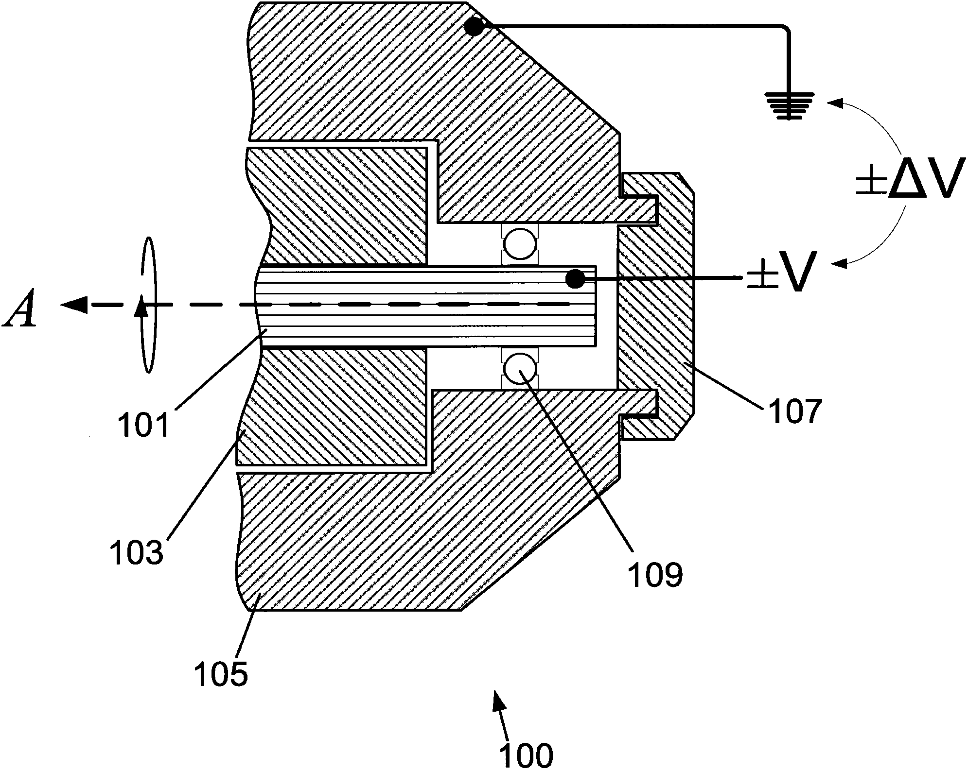
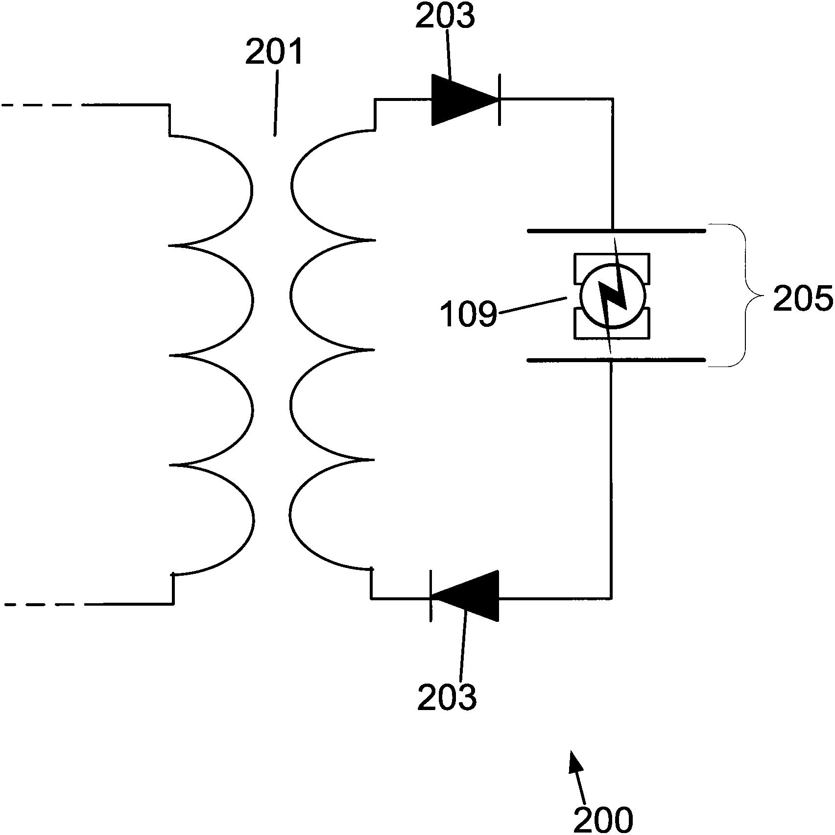
[0016] The present invention is concerned with electrical energy usage and generation, and the principles of the invention allow for an efficient and economical solution to charging / discharging bearings in a form that is easy to install and easy to maintain. The systems and devices of the present invention can be used in a wide range of applications including locomotive, industrial and construction energy use and generation applications, etc., without substantial supply or retrofit costs. Specific, non-limiting examples include industrial and consumer grade generators, such as stand-alone generators and generators that are part of larger machines or structures.

[0017] Furthermore, while the principles of the present invention are described by way of example with respect to conductive bearing arrangements, it will be appreciated that the principles of the present invention can also be used in other environments, including those using more expensive ceramic or other insulating ...


PUM


Abstract

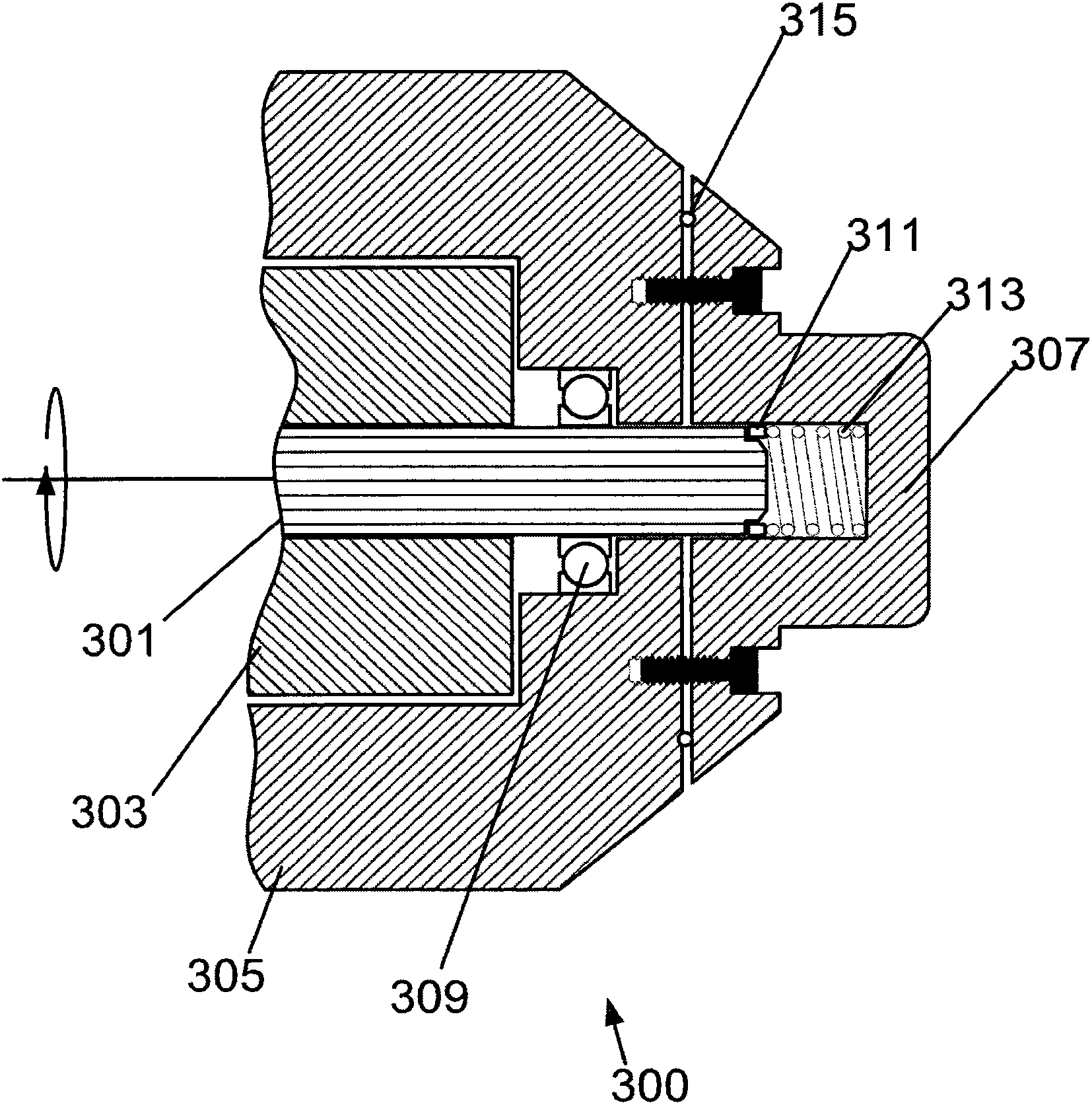
An assembly, system and method are provided for discharging a rotating shaft encompassed by a stationary housing. The system includes an annular charge-dissipating component and a biasing element oriented to apply an axial force to the charge-dissipating component, holding it in contact with the shaft and the housing while the shaft is rotating. The biasing element may be a coil spring or a wave spring. A shaft grounding upgrade kit includes a conductive ring member and a cylindrical spring having a diameter that is the same as that of the conductive ring member. The spring constant of the cylindrical spring is such that the spring holds the conductive ring member within the housing in contact with the shaft and the housing. The conductive ring member may be constructed of gray iron and the cylindrical spring is one of a wave spring and a coil spring.

Description

technical field [0001] The present invention relates generally to rotating electrical shafts, and more particularly to a charge dissipation device for discharging a charged shaft to prevent damaging discharges across bearings of the shaft. Background technique [0002] The phenomenon of induction, ie the interaction between an electric field and a magnetic field to generate a force or create an electric current, is exploited in a variety of applications across a wide range of industries. In virtually all cases where electrical energy is generated or converted into physical motion, the energy of electrical induction is utilized. [0003] For example, rotation of a magnetic array within a conductor network (or rotation of a conductive coil within an array of magnets) generates an electrical current that can be controlled as usable electrical energy. This principle finds application in generators for industrial applications, locomotive applications, municipal power application...

Claims


Application Information

Patent Timeline
IPC IPC(8): H01R4/66F16C19/49
CPCF16C19/52H02K5/1732H02K11/0089F16C19/06F16C41/002H02K11/40
Inventor J·M·鲍曼
Owner CATERPILLAR INC
Learn More