Hydraulic system of buffering cylinder of forging manipulator

A forging manipulator and hydraulic system technology, applied to the driving device of the forging press, fluid pressure actuating device, etc., can solve the problems of inability to realize the active control of the buffer cylinder, limiting the flexibility of the clamp of the manipulator, and the complex structure of the buffer cylinder , to achieve the effect of complete functions, simple control and large buffer force

Inactive Publication Date: 2012-10-24
ZHEJIANG UNIV
View PDF5 Cites 10 Cited by
  • Summary
  • Abstract
  • Description
  • Claims
  • Application Information

AI Technical Summary

Problems solved by technology

[0002] The special working condition linked with the forging press requires that the tongs of the forging manipulator must have both passive buffering and active control functions in the horizontal direction. Most buffer cylinder hydraulic systems currently exist only have passive buffering functions and cannot realize Active control of the buffer cylinder, limiting the flexibility of the manipulator clamp in the horizontal direction
After searching the existing technology, it is found that the Chinese invention patent with the application number 200910153528.1 records a "horizontal buffer cylinder hydraulic system for forging manipulator", which realizes passive buffering and active buffering by means of a hydraulic cylinder with multiple chambers and piston rods. control function, but the structure of the buffer cylinder described in this patent is relatively complicated, and the force buffer system and the displacement closed-loop control system are coupled in the same oil circuit

Method used


Image

  • Hydraulic system of buffering cylinder of forging manipulator

Examples


Embodiment Construction

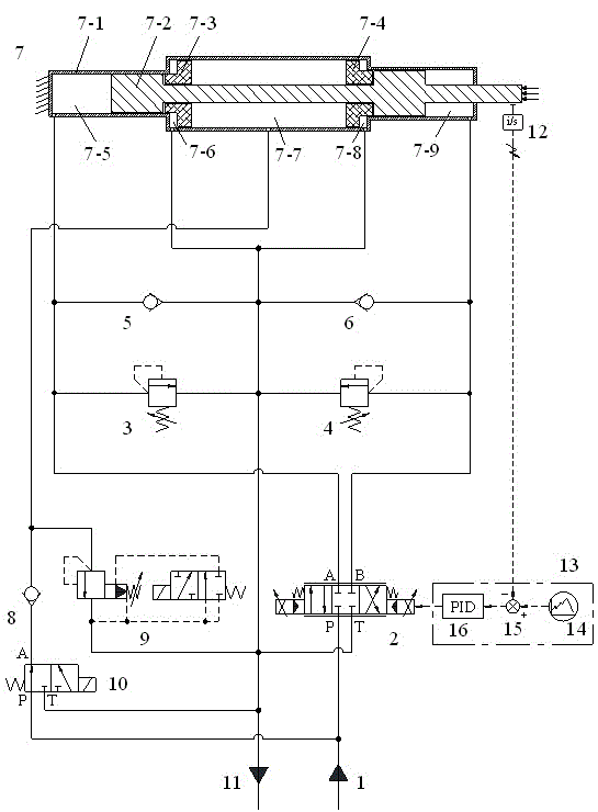
[0015] The present invention will be further described below in conjunction with the accompanying drawings and examples of implementation.

[0016] As shown in the drawings, the present invention includes a buffer cylinder 7; the P port of the proportional directional valve 2 is connected with the oil supply port 1 and the P port of the electromagnetic directional valve 10 respectively; the A port of the proportional directional valve 2 is connected with the rear chamber overflow The inlet of the flow valve 3, the outlet of the one-way valve 5 in the rear chamber, and the rear chamber 7-5 of the buffer cylinder are connected; the B port of the proportional directional valve 2 is connected with the inlet of the relief valve 4 in the front chamber and the outlet of the one-way valve 6 in the front chamber respectively. , the buffer cylinder front cavity 7-9 connection; the T port of the proportional directional valve 2 is respectively connected with the outlet of the pilot relief...


PUM


Abstract

The invention discloses a hydraulic system of a buffering cylinder of a forging manipulator. The hydraulic system comprises an oil source oil supply opening, a proportional direction valve, an overflow valve, a one-way valve, the buffering cylinder, a pilot overflow valve, an electromagnetic direction valve, an oil source oil return opening, a displacement sensor, a displacement set signal, a subtractor and a PID (proportion integration differentiation) controller. A combined type multi-cavity structure of the buffering cylinder of the forging manipulator is utilized, a passive buffering system with the pilot overflow valve and an active displacement closed-loop control system with the proportional direction valve are integrated on the buffering cylinder, a passive buffering function of a clamp of the manipulator can be realized, and furthermore, a required displacement closed-loop control function of the buffering system of the forging manipulator is also realized. The hydraulic system has the advantages of simplicity in control and multiple functions. By a multi-cavity buffering mode of the buffering cylinder of the system, higher buffering force can be provided by the buffering cylinder with the same diameter. Besides, because proportional control elements are fewer, the reliability of the system is high.

Description

technical field [0001] The invention relates to a buffer cylinder hydraulic system, in particular to a buffer cylinder hydraulic system of a forging manipulator. Background technique [0002] The special working condition linked with the forging press requires that the tongs of the forging manipulator must have both passive buffering and active control functions in the horizontal direction. Most buffer cylinder hydraulic systems currently exist only have passive buffering functions and cannot realize The active control of the buffer cylinder limits the flexibility of the manipulator clamp in the horizontal direction. After searching the existing technology, it is found that the Chinese invention patent with the application number 200910153528.1 records a "horizontal buffer cylinder hydraulic system for forging manipulator", which realizes passive buffering and active buffering by means of a hydraulic cylinder with multiple chambers and piston rods. control function, but the...

Claims


Application Information

Patent Timeline
Patent Type & Authority Applications(China)
IPC IPC(8): B21J9/12F15B15/22F15B15/28
Inventor 周华侯交义傅新杨华勇
Owner ZHEJIANG UNIV
Why Eureka
Try Eureka