Injection molding machine

A technology of injection molding machine and servo motor, applied in the field of injection molding machine, can solve the problems of low repeatability, easily damaged hydraulic components, damaged asynchronous motor, etc., and achieve the effect of prolonging the life of hydraulic system, good energy saving performance and high repeatability

Inactive Publication Date: 2012-10-24
宁波高新区安立特电气科技有限公司
View PDF0 Cites 6 Cited by
  • Summary
  • Abstract
  • Description
  • Claims
  • Application Information

AI Technical Summary

Problems solved by technology

The existing injection molding machine servo control system includes a control valve, an oil tank, an oil outlet pipe, an oil return pipe, a quantitative pump and a hydraulic cylinder. The oil outlet pipe and the oil return pipe are connected between the control valve and the oil tank, and the hydraulic cylinder is used as the power source of the injection molding machine. , the control valve controls the on-off of the oil circuit in the two chambers of the hydraulic cylinder, and the quantitative pump is set on the oil outlet pipe to provide pressure for the entire hydraulic system. The existing quantitative pump is usually driven by an asynchronous motor, and the control accuracy of the asynchronous motor is poor. In order to ensure the normal operation of the injection molding machine during use, the asynchronous motor starts at full power for every action of the injection molding machine, and the entire hydraulic system is always in the hydraulic state when the asynchronous motor starts at full power. The use of posed the following problems:
[0003] 1. The asynchronous motor is always in full power operation, which will cause an increase in energy consumption and a corresponding increase in heat generation. Not only the asynchronous motor is easily damaged due to excessive heat, but it will also cause the temperature of the entire workshop to rise. Both equipment and personnel health will be affected;
[0004] 2. The starting current of the asynchronous motor is large, and in a workshop with multiple injection molding machines, the capacity of the entire power grid is required to be large;
[0005] 3. The hydraulic system is always in the hydraulic state when the asynchronous motor starts at full power, and the hydraulic components in the entire system are easily damaged, which affects the service life of the hydraulic system, thereby causing an increase in operating costs;
[0006] 4. The response speed of the asynchronous motor is slow, which is not conducive to the precise control in the injection molding process, and the repeatability is low
[0007] Due to the above shortcomings, the existing injection molding machines cannot effectively meet people's use requirements, so it is necessary to improve

Method used


Image

  • Injection molding machine

Examples


Embodiment 1

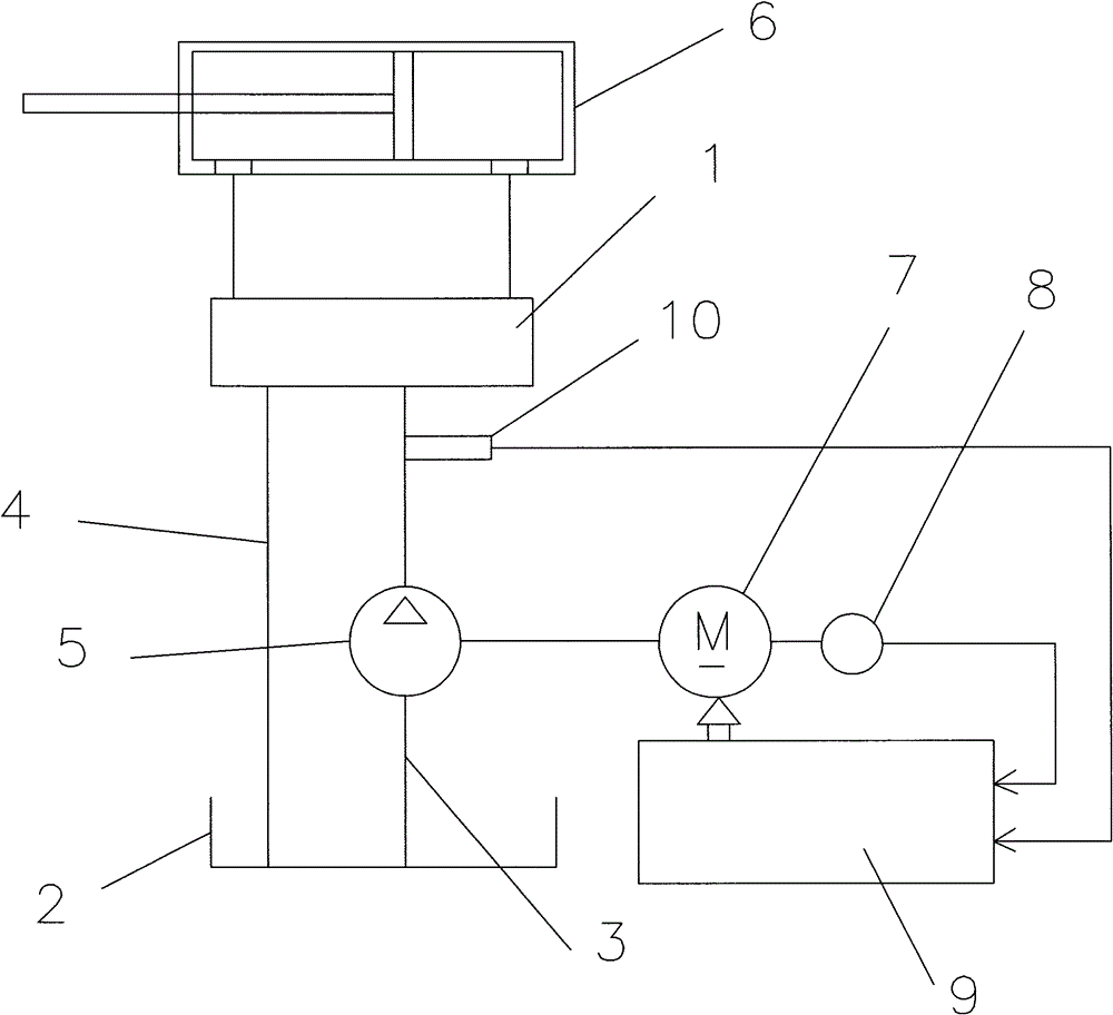
[0016] Such as figure 1 As shown, the injection molding machine described in this embodiment includes a servo control system, and the servo control system includes a control valve 1, an oil tank 2, an oil outlet pipe 3, an oil return pipe 4, a quantitative pump 5 and a hydraulic pressure as the power of the injection molding machine. The oil cylinder 6, the oil outlet pipe 3 and the oil return pipe 4 are connected between the control valve 1 and the oil tank 2, and the hydraulic oil cylinder 6 is provided with two front and rear chambers separated by the piston, and the two chambers are respectively connected to the control valve. The valve 1 is connected, the quantitative pump 5 is arranged on the oil outlet pipe 3, the servo control system also includes a servo motor 7, a rotary encoder 8, a servo drive controller 9 and a pressure sensor 10, and the servo motor 7 is connected to the quantitative The pump 5 is connected by transmission; the rotary encoder 8 is set on the serv...


PUM


Abstract

The invention discloses an injection molding machine, comprising a servo-controlled system, wherein the servo-controlled system comprises a control valve, an oil tank, an oil outlet pipe, an oil return pipe, a fixed displacement pump and a hydraulic cylinder as the power of the injection molding machine, the oil outlet pipe and the oil return pipe are connected with the control valve and the oil tank and are arranged between the control valve and the oil tank, front and rear cavities separated by a piston are arranged in the hydraulic cylinder, the two cavities are respectively connected with the control valve, the fixed displacement pump is arranged on the oil outlet pipe, the servo-controlled system further comprises a servo motor, a rotary encoder, a servo drive controller and a pressure sensor, the servo motor is connected with the fixed displacement pump in a transmission way; the rotary encoder is arranged on the servo motor, and the output signals are input to the servo drive controller; the pressure sensor is arranged on the oil outlet pipe, and the output signals are input to the servo drive controller, and the servo drive controller is electrically connected with the servo motor. The injection molding machine has the following advantages: 1, good energy-saving performance; 2, quick respond speed; 3, high repeat precision; and 4, prolonged service life of the hydraulic system.

Description

technical field [0001] The invention relates to an injection molding machine. Background technique [0002] With the development of society, injection molding machines are used more and more widely. The existing injection molding machine servo control system includes a control valve, an oil tank, an oil outlet pipe, an oil return pipe, a quantitative pump and a hydraulic cylinder. The oil outlet pipe and the oil return pipe are connected between the control valve and the oil tank, and the hydraulic cylinder is used as the power source of the injection molding machine. , the control valve controls the on-off of the oil circuit in the two chambers of the hydraulic cylinder, and the quantitative pump is set on the oil outlet pipe to provide pressure for the entire hydraulic system. The existing quantitative pump is usually driven by an asynchronous motor, and the control accuracy of the asynchronous motor is poor. In order to ensure the normal operation of the injection moldin...

Claims


Application Information

Patent Timeline
Patent Type & Authority Applications(China)
IPC IPC(8): B29C45/82
Inventor 丁长志
Owner 宁波高新区安立特电气科技有限公司
Why Eureka
Try Eureka