
Multifunctional hydraulic machine

A hydraulic press, multi-functional technology, applied in punching machines, presses, manufacturing tools, etc., can solve problems such as waste, energy consumption of reaction force of master cylinder, etc., to achieve the effect of reducing weight and preventing performance

Inactive Publication Date: 2012-10-24
HENAN UNIV OF SCI & TECH
View PDF13 Cites 29 Cited by
  • Summary
  • Abstract
  • Description
  • Claims
  • Application Information

AI Technical Summary

Problems solved by technology

[0004] The purpose of the present invention is to provide a multi-functional hydraulic press to solve the problem of waste of energy consumption caused by the reaction force of the blank holder cylinder to the main cylinder during the forming operation of the existing hydraulic press

Method used


Image

  • Multifunctional hydraulic machine
  • Multifunctional hydraulic machine
  • Multifunctional hydraulic machine

Examples


Embodiment Construction

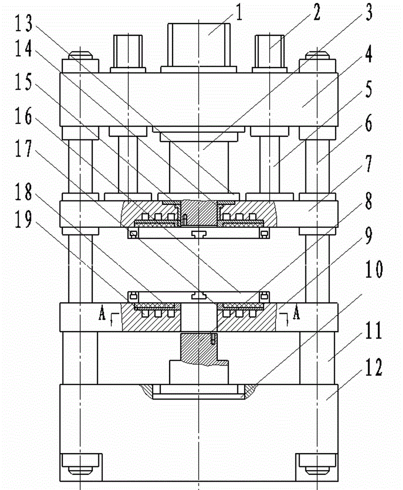
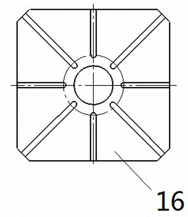
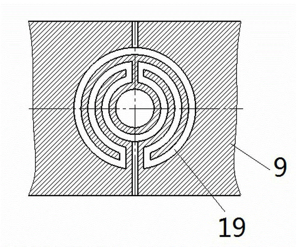
[0024] Embodiment 1 of a kind of multifunctional hydraulic press is as Figure 1~4 Shown: including the column 6, the upper beam 4, the blank holder slider 7, the fixed worktable 9 and the lower beam 12 are arranged at intervals along the vertical direction on the column 6, wherein the upper beam 4, the fixed workbench 9 and the lower beam 12 are connected with the column 6 is fixedly matched, and the blank holder slider 7 is guided and slidably matched with the column 6. The upper beam 4 is provided with a main cylinder 1 and a blank holder cylinder 2. There are four (or two) clamp cylinders and they are circumferentially distributed on the periphery of the master cylinder 1. The blank holder cylinder 2 is fixed to the upper beam 4 The connected blank holder cylinder body and the blank holder cylinder piston 5 fixedly connected with the blank holder slide block 7 . The master cylinder 1 includes a master cylinder body fixedly connected to the upper crossbeam 4 and a master c...


PUM


Abstract

The invention relates to a multifunctional hydraulic machine which comprises a vertical column, a side pressing sliding block and a side pressing cylinder, wherein the side pressing sliding block is assembled on the vertical column in a guide sliding mode, and the side pressing cylinder drives the side pressing sliding block to vertically move along the vertical column. An upper transverse beam is fixedly arranged on the hydraulic machine and above the side pressing sliding block. The side pressing cylinder comprises a side pressing cylinder body fixedly arranged on the upper transverse beam and a side pressing cylinder piston fixedly arranged on the side pressing sliding block. A main cylinder is arranged on the upper transverse beam and comprises a main cylinder body fixedly arranged the upper transverse beam and a main cylinder piston for installing a corresponding upper pressing head. The side pressing sliding block is provided with an upper through hole which penetrates through the upper end face and the lower end face of the side pressing sliding block to enable the upper pressing head installed on the main cylinder piston to penetrate through. The multifunctional hydraulic machine solves the problem that energy waste is caused due to the fact that the side pressing cylinder exerts reacting force on the main cylinder when the existing hydraulic machine performs forming operation.

Description

technical field [0001] The invention relates to a hydraulic press for metal plastic processing, in particular to a multifunctional hydraulic press suitable for metal cold plastic forming or thermoplastic forming such as closed forging, continuous extrusion, sheet material stretching, etc. Background technique [0002] Hydraulic press occupies a pivotal position in today's plastic forming technology. The use of suitable equipment can simplify the forming process and form parts that are difficult to form. Existing hydraulic machines such as the Chinese patent CN2685058Y disclose a kind of "up and down are double-action adjustable hydraulic machines", including a main body, the main body includes a column and an upper beam fixed on the column along the vertical direction, a fixed workbench and a lower The beam, the column between the upper beam and the workbench is also guided and slidably equipped with a main slider and a blank holder slider. The upper beam is fixed with a mas...

Claims


Application Information

Patent Timeline
IPC IPC(8): B30B1/32B30B15/02B30B15/34
Inventor 杨永顺杨茜虞跨海陈拂晓郭俊卿于华宋志真张彦敏
Owner HENAN UNIV OF SCI & TECH
Learn More