Facility for automatically collecting waste liquid in volumetric flasks

An automatic collection and volumetric bottle technology, which is used in emptying containers, bottle filling, liquid treatment, etc., can solve the problems of time-consuming and laborious recycling and collection of waste liquid, physical harm to workers, and heavy labor for workers. Hazards, easy post-processing, and the effect of ensuring cleanliness

Inactive Publication Date: 2012-10-24
CENT TESTING INT GRP CO LTD
View PDF7 Cites 32 Cited by
  • Summary
  • Abstract
  • Description
  • Claims
  • Application Information

AI Technical Summary

Problems solved by technology

At present, the laboratory processes a large amount of waste liquid, which is only collected by manual operation, and the workload of the staff is large; on the other hand, the waste liquid contains organic solvent components, which are highly toxic and volatile, and are particularly harmful to the health of the staff. Big
Recycling and collecting waste liquid has become a time-consuming, laborious, dirty and toxic work. There is an urgent need for an automatic waste liquid collection device to improve the existing problems
And the containers containing waste liquid are also different. The containers commonly used to store sample solution waste liquid for a long time in the laboratory are mainly test tubes and volumetric flasks. The difference in the shape of the container makes it difficult to realize automatic collection of waste liquid
For example, the volumetric flask for storing the waste liquid of the sample solution needs to unscrew the ground glass stopper, and the thin bottleneck also slows down the flow rate of the waste liquid; the test tube for storing the waste liquid of the sample solution needs to unscrew the cap of the test tube, the tube type Restriction makes it difficult to pour solution quickly

Method used


Image

  • Facility for automatically collecting waste liquid in volumetric flasks
  • Facility for automatically collecting waste liquid in volumetric flasks
  • Facility for automatically collecting waste liquid in volumetric flasks

Examples


Embodiment Construction

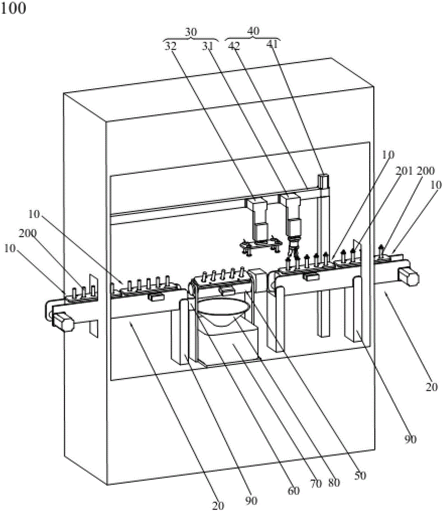
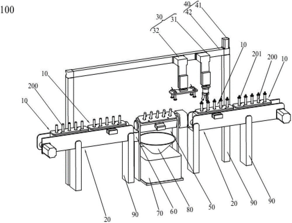
[0022] The present invention will be further described below in conjunction with the accompanying drawings. The technical solution adopted in the present invention is: a volumetric flask waste liquid automatic collection device 100, such as figure 1 , 2 As shown, it includes a fixing device 10, a power transmission device 20, a single-axis robot 40, a handling device 30, and a rotating fixture 50:

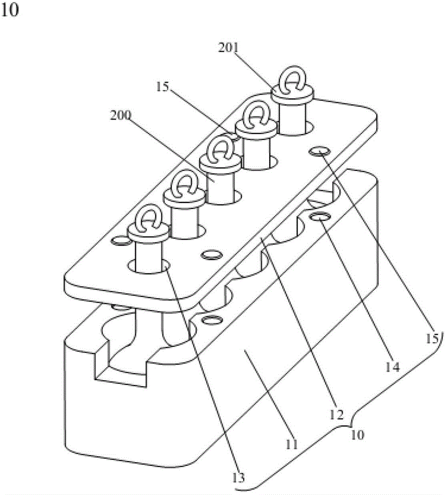
[0023] The volumetric flask waste liquid automatic collection device 100, the fixing device 10 includes a container box 11, a container cover 12, such as image 3 As shown, the container box 11 can place a plurality of containers 200, covered by the container cover 12 with holes to form a whole fixing device 10, which can pour out waste liquid at one time and improve work efficiency; a set of volumetric bottle waste liquid The automatic collection device 100 is provided with multiple sets of fixing devices 10 of different models, which can improve work efficiency and has strong pr...


PUM


Abstract

The invention discloses facility for automatically collecting waste liquid in volumetric flasks. The technical scheme of the facility includes that the facility for automatically collecting waste liquid comprises a fixing device, a power transmission device, a single-shaft robot, a transportation device and a rotary fixture. A container containing waste liquid is arranged on the fixing device, the fixing device on a conveyor is driven by a motor to be conveyed to an operation table, a cover of the container is unscrewed and placed in a cover collecting disc by a manipulator, the fixing device is transported to the rotary fixture above a waste liquid collecting barrel by a sucker, is fixed in a fixed sleeve, is turned and shaken by a rotating cylinder so that the waste liquid can be poured out, and finally is transported to the conveyor to be moved out of the operation table. The facility for automatically collecting waste liquid is simple in structure, convenient to operate, labor-saving, material-resource-saving, time-saving, safe, quick, high-efficient and automatic. Frequent working procedures are avoided.

Description

technical field [0001] The invention relates to a waste liquid recovery and treatment device, in particular to an automatic collection device capable of collecting chemical waste liquid quickly, safely and efficiently. Background technique [0002] With the improvement of people's living standards, more and more products have become the objects to be tested, and the samples need to be prepared into the required state to be tested through sample pretreatment, and a large amount of waste liquid is often generated during the sample pretreatment stage, and The prepared sample solution often needs to be kept for 15 days in order to prepare for rechecking the accuracy of the test results. These sample solution wastes cannot be dumped at will, and need to be recycled to reduce adverse impacts on the environment. At present, the laboratory processes a large amount of waste liquid, which is only collected by manual operation, and the workload of the staff is large; on the other hand...

Claims


Application Information

Patent Timeline
Patent Type & Authority Applications(China)
IPC IPC(8): B67C9/00B67B7/14B65G47/91B65G47/92
Inventor 苏康宇董宁李波朱平郭勇
Owner CENT TESTING INT GRP CO LTD
Why Eureka
Try Eureka