
Pouring machine and pouring method for concrete of road shoulder on high-speed railroad bed section

A technology of high-speed railway and pouring method, which is applied in the direction of infrastructure engineering, construction, etc., can solve the problems of difficult control of slope, difficulty in operation and standing, and low construction efficiency, so as to improve internal quality and appearance quality, reduce construction safety risks, and improve The effect of construction progress

Active Publication Date: 2012-10-24
THE 2ND ENG CO LTD OF CHINA RAILWAY 17 BUREAU GRP
View PDF5 Cites 10 Cited by
  • Summary
  • Abstract
  • Description
  • Claims
  • Application Information

AI Technical Summary

Problems solved by technology

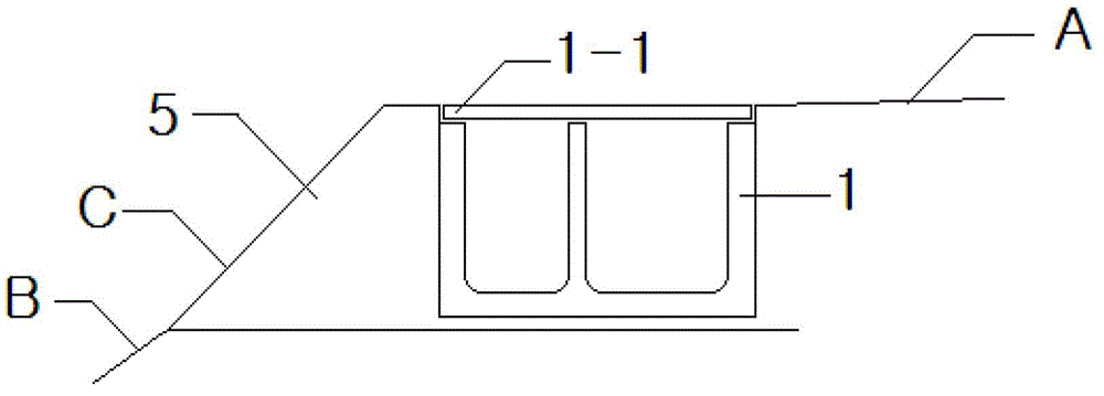
[0003] At present, the problems and difficulties existing in construction include: the concrete is sent to the pouring point by the tank truck through the formed roadbed, and the concrete is manually poured across the cable trough to the outside of the cable trough for pouring, which is labor-intensive and low in construction efficiency; workers stand on the roadbed It is difficult to stand up while operating on the slope. Once the foot is unstable, it is very likely to roll to the bottom of the slope and fall, which has a certain safety risk; Concrete poured on the slope cannot be vibrated normally, and it is difficult to guarantee the compactness of the concrete

Method used


Image

  • Pouring machine and pouring method for concrete of road shoulder on high-speed railroad bed section
  • Pouring machine and pouring method for concrete of road shoulder on high-speed railroad bed section
  • Pouring machine and pouring method for concrete of road shoulder on high-speed railroad bed section

Examples


Embodiment Construction

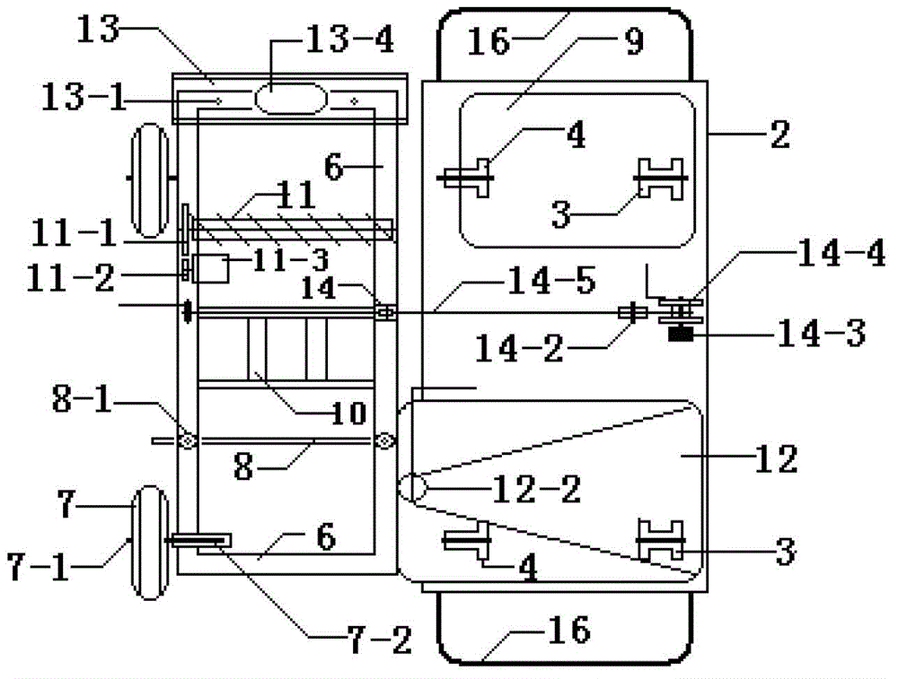
[0028] Such as Figure 2~Figure 6 As shown, a high-speed railway subgrade section road shoulder concrete pouring machine includes a rectangular frame 2, a hopper is arranged on the front part of the frame; The generator 13-4 runs. Respectively arrange a pair of walking wheels before and after the frame below and just place on the walking track 15 on the roadbed cable trough. A work frame 6 is hinged on the left or right side of the frame (the present embodiment is the left side). The paving scraper 8, the vibrating operation pedal 10, the leveling coiler 11, and the plastering panel 13 are sequentially arranged on the work frame from the front to the rear, and the concrete can be paved and scraped, vibrated, leveled, Wiping equal work.

[0029] The pouring machine in this embodiment is also provided with a working frame retractable device: including a low-position fixed pulley 14-2 on the frame 2, a lifting column 14-3 and a ratchet-type hand-operated lifting windlass 14-4 ...


PUM


Abstract

The invention discloses a pouring machine and a pouring method for concrete of a road shoulder on a high-speed railroad bed section. The pouring machine comprises a rectangular frame, wherein a hopper is arranged on the upper front part of the rectangular frame; a generator is arranged on the rear part of the rectangular frame; a pair of travelling wheels are respectively arranged on front and rear sides under the rectangular frame and are just arranged on a travelling rail on a railroad bed cable slot; an operating shelf is hinged with one side of the rectangular frame; an auxiliary wheel is arranged on a longitudinal beam outside the operating shelf; and a paving scraper, a vibrating operation pedal, a leveling roll and a plaster plate are successively arranged above the operating shelf from front part to rear part. During a pouring process, the travelling wheels of the frame and the travelling rail on the railroad bed cable slot are arranged on the railroad bed in a matching form, the operating shelf is placed bias above a concrete pouring area and the auxiliary wheel is arranged on a side slope of the railroad bed; the hopper is used for receiving and storing materials and the concrete is poured into the pouring area through a discharging port; the paving scraper is used for uniformly paving and scraping the concrete; after vibrating, the leveling roll is used for upward leveling the downward flowing concrete; and lastly, the plaster plate is used for realizing the smoothing of the concrete surface.

Description

technical field [0001] The invention relates to a concrete pouring and forming device and process, in particular to a small-scale concrete pouring-in-place construction machine tool and a pouring method for a road shoulder part of a high-speed railway embankment slope. Background technique [0002] The prefabricated cable trenches in the embankment section of the high-speed railway are buried 10cm inside the road shoulders. The shoulders outside the cable trenches are easily damaged by rainwater all year round, and it is difficult to repair them due to their thin geometric dimensions. In order to improve the stability and durability of the road shoulder, the top 60cm area of ​​the outer shoulder of the cable trough is designed to use cast-in-place concrete slope protection, and the lower part adopts other forms of masonry slope protection. During the pouring-in-situ construction of road shoulder concrete, the concrete slope protection surface C should not only be firmly conn...

Claims


Application Information

Patent Timeline
Patent Type & Authority Applications(China)
IPC IPC(8): E02D15/02
Inventor 王新民丁愿文霍继军张翠芹于广志王郭波陈江夏桑梅青
Owner THE 2ND ENG CO LTD OF CHINA RAILWAY 17 BUREAU GRP
Learn More