
Detecting device capable of realizing drill hole three-dimensional imaging and method thereof

A technology of three-dimensional imaging and detection equipment, which is applied in the directions of surveying, earthwork drilling and production, wellbore/well components, etc., which can solve the problems of not fully representing the inclination angle of borehole 1, increasing on-site workload, and loss of sensing accuracy, etc., to achieve The effect of enriching various detection results

Active Publication Date: 2012-10-24
武汉岩海工程技术有限公司
View PDF6 Cites 18 Cited by
  • Summary
  • Abstract
  • Description
  • Claims
  • Application Information

AI Technical Summary

Problems solved by technology

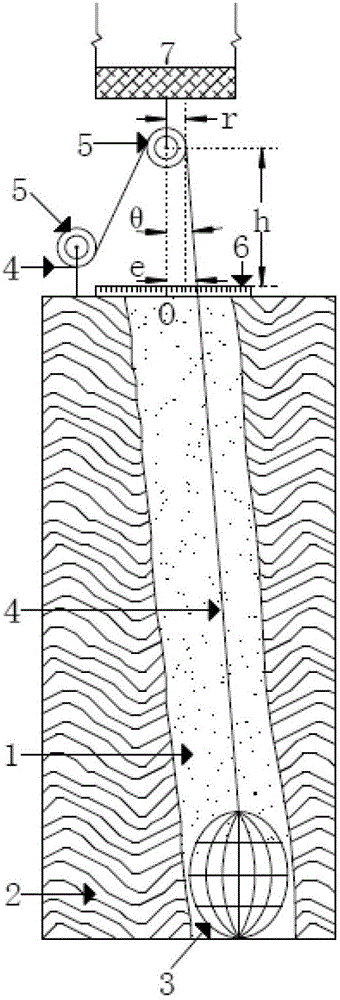
[0031] ① The detection of aperture and hole inclination requires different devices, and the detection cannot be completed at one time, which artificially increases the workload on site;
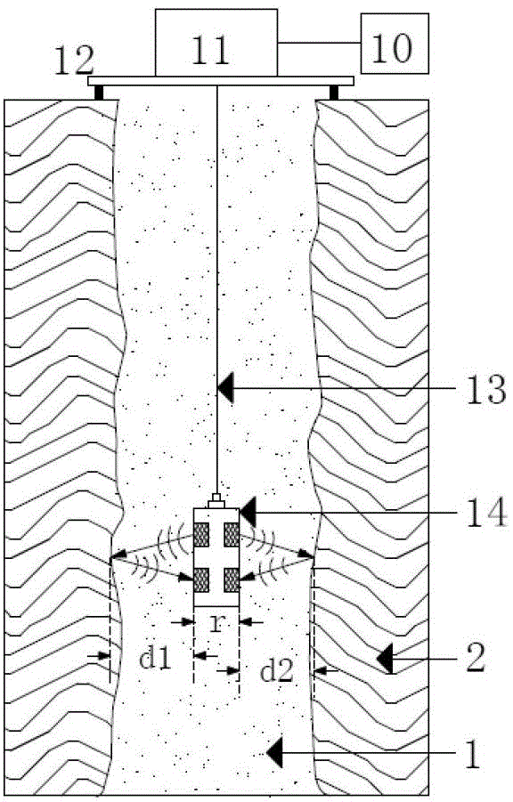
[0032] ② The accuracy of aperture detection is low; Figure 3.2 , the circular motion of the larger stroke of the end b of the measuring arm 22 is converted into the up and down linear motion of the smaller stroke of the sliding rod 26, and the large stroke to small stroke means the loss of sensing accuracy;
[0034] ④ Hole inclination detection uses a separate traditional inclinometer 28; in actual testing, the traditional inclinometer 28 needs to rely on its own weight to completely contact the inner wall of a certain orientation of the borehole 1, so what is detected is the inclination angle of the inner wall at this orientation, and Cannot fully represent the inclination angle of borehole 1;
[0035] ⑤Whether the traditional inclinometer 28 can fully contact the inner wall of the borehole 1, it is necessary to try different measuring points at the opening of the borehole 1, and combine the depth position of the traditional inclinometer 28, the aperture of the borehole 1 and other information to give Therefore, the detection process is complicated, and the detection results need to rely on manual experience

Method used


Image

  • Detecting device capable of realizing drill hole three-dimensional imaging and method thereof
  • Detecting device capable of realizing drill hole three-dimensional imaging and method thereof
  • Detecting device capable of realizing drill hole three-dimensional imaging and method thereof

Examples


Embodiment Construction

[0102] The detection device capable of realizing three-dimensional imaging of boreholes will be described in detail below in conjunction with the accompanying drawings and embodiments:

[0103] 1. Overall structure

[0104] Such as Figure 5 , the device includes a detection instrument 20 and an electric winch 30 on the ground, and is provided with downhole sensors. 27. The rotating shaft 36, the main circuit board 33, the long rod 39, the measuring arm 22, the measuring arm circuit board 37, and the damping disc 38;

[0105] Its location and connection relationship are:

[0106] The downhole sensor is connected with the detection instrument 20 on the ground through the cable 13;

[0107] The top of the sealing cylinder 32 is provided with a cable socket 31 for connecting with the cable 13;

[0108] The interior of the sealing cylinder 32 is provided with a main circuit board 33, an epoxy resin waterproof layer 35, an internal connecting wire 34 and a pressure spring 27;

...


PUM


Abstract

The invention discloses a detecting device capable of realizing drill hole three-dimensional imaging and a method thereof, and relates to the techniques of constructional engineering detection. The detecting device comprises a detector (20) on the ground, an electric winch (30) and a downhole sensor. The downhole sensor comprises a seal cylinder (32), a cable socket (31), a main circuit board (33), an epoxy resin waterproof layer (35), an internal connecting wire (34), a pressure spring (27), a rotary shaft (36), a long rod (39), a detecting arm (22), a detecting arm circuit board (37), and a damping disk (38). By the detecting device, detecting method is simplified, work efficiency is enhanced, and detecting precision is improved. By the three-dimensional imaging, comprehensive and visualized detecting results are provided. Aperture and hole deviation curves under different definitions can be calculated through different mathematical methods on the basis of three-dimensional imaging pictures, so that rich and diversified detecting results are provided. The detecting device is applicable to detection of aperture and hole deviation is constructional engineering.

Description

technical field [0001] The invention relates to construction engineering detection technology, in particular to a detection device capable of realizing borehole three-dimensional imaging and a method thereof. Background technique [0002] Bored pile is one of the common foundation pile forms in construction engineering. Its function is to transfer the load of the superstructure to the deep stable soil layer or rock layer, and reduce the uneven settlement of the superstructure. The construction of bored piles is divided into two stages: "drilling" and "pouring concrete" into the borehole. The drilling operation in the first stage is completed underground and with water injection, so quality control is difficult, and sometimes complex geological conditions may easily cause mistakes in construction, which may eventually lead to different diameters (apertures) of boreholes, and holes along gravity The direction is tilted (hole skew) and other problems. [0003] After pouring c...

Claims


Application Information

Patent Timeline
IPC IPC(8): E21B47/002E21B47/022E21B47/08E21B47/085
Inventor 杨燕军杨光
Owner 武汉岩海工程技术有限公司
Learn More