Mounting structure and mounting method of air valve seat ring

A technology of valve seat ring and installation structure, which is applied in the direction of valve devices, valve lifts, mechanical equipment, etc., and can solve problems such as unfavorable valve heat dissipation, reduction of the bonding area of ​​valve seat ring holes, and reduced heat transfer efficiency

Inactive Publication Date: 2012-10-24
SAIC MOTOR
View PDF5 Cites 5 Cited by
  • Summary
  • Abstract
  • Description
  • Claims
  • Application Information

AI Technical Summary

Problems solved by technology

However, features such as chamfering or rounding 14 actually reduce the bonding area between the valve seat ring hole 11 and the valve seat ring 13
Resulting in lower heat transfer efficiency, which is not conducive to heat dissipation of the valve

Method used


Image

  • Mounting structure and mounting method of air valve seat ring
  • Mounting structure and mounting method of air valve seat ring
  • Mounting structure and mounting method of air valve seat ring

Examples


Embodiment Construction

[0024] Specific embodiments of the present invention will be described in detail below. The following embodiments are only an example of the technical solutions of the present invention, and should not be construed as limiting the protection scope of the present invention.

[0025] Valve seat ring installation structure

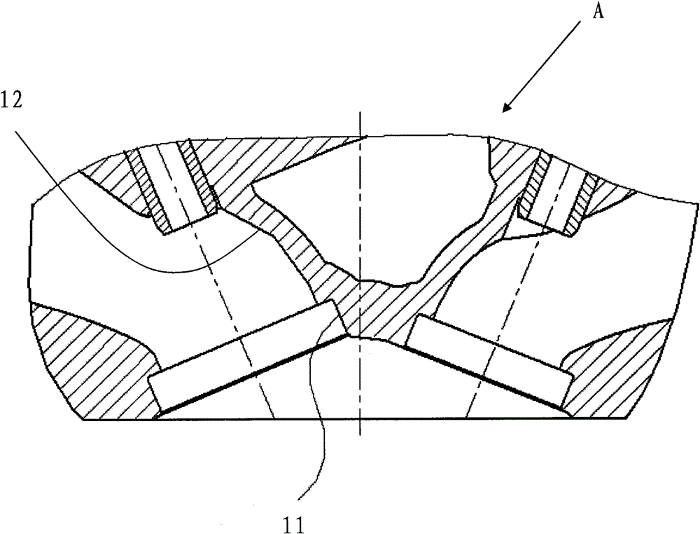
[0026] Existing internal combustion engines / engine assemblies mainly include engine blocks, cylinder heads and valves. The cylinder head is fixed to the engine body and has an air passage 12 .

[0027] Such as figure 1 As shown, the structure of the cooperation between the cylinder head A of the internal combustion engine / engine assembly and the valve seat ring is: processing is performed at the joint (air outlet) between the air passage 12 of the cylinder head A and the engine combustion chamber to form a stepped valve seat ring hole 11 .

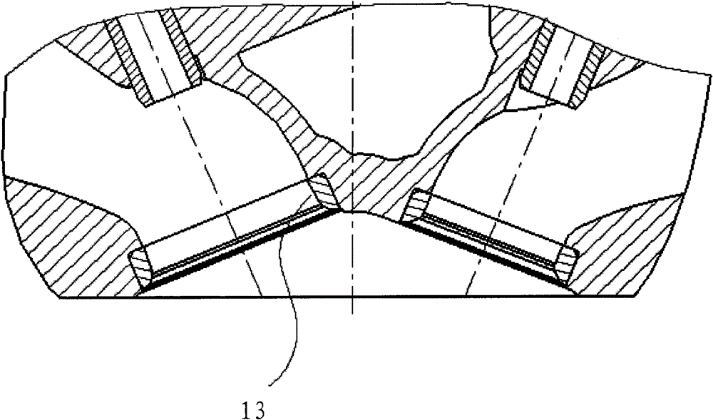
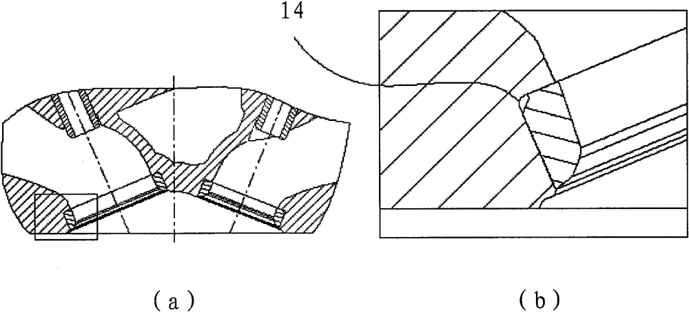
[0028] Therefore, the valve seat mounting structure of the present embodiment is as follows: Figure 4 As shown, i...


PUM


Abstract

The invention provides a mounting structure of an air valve seat ring, which is characterized by comprising an air cylinder cover, an air channel arranged in the air cylinder cover, and a pre-cast air valve seat ring which is pre-arranged at a jointing part of the air channel and an engine combustion room, wherein the air valve seat ring is made of a metal material and is commonly manufactured by a power metallurgy process.

Description

technical field [0001] The invention relates to a valve seat ring installation structure and installation method, in particular to a valve seat ring installation structure and installation method that cooperate with an internal combustion engine / engine valve. Background technique [0002] In the prior art, the common structure of the cylinder head A of the internal combustion engine / engine and the valve seat ring is as follows: figure 1 Shown: the air passage 12 of the cylinder head A is processed at the joint (air outlet) of the engine combustion chamber to form a stepped valve seat ring hole 11. And, if figure 2 As shown, the valve seat ring 13 is pressed into the above-mentioned valve seat ring hole 11 . [0003] The valve seat ring 13 plays a very important function in the working process of the internal combustion engine-sealing the valve and transferring the heat of the valve. The heat of the valve comes from the combustion of the mixture in the engine cylinder. If...

Claims


Application Information

Patent Timeline
IPC IPC(8): F01L3/06F02F1/42
CPCY02T10/146Y02T10/12
Inventor 宋文倡
Owner SAIC MOTOR
Why Eureka
Try Eureka