Power generation method and device of H-bridge

A technology of power generation device and buffer device, applied in the direction of engine components, machines/engines, mechanical equipment, etc., can solve the problems of difficult breakthrough in water energy utilization efficiency, depletion of water conservancy power generation resources, and difficulty in development and utilization, etc., to achieve water energy utilization. High efficiency, low cost and low water consumption

Active Publication Date: 2012-10-24
台山市共荣食品有限公司
View PDF5 Cites 1 Cited by
  • Summary
  • Abstract
  • Description
  • Claims
  • Application Information

AI Technical Summary

Problems solved by technology

[0002] At present, my country's fresh water resources are relatively short, and the available hydropower resources are becoming increasingly exhausted. It is difficult to develop and utilize some hydropower resources with small capacity and low water head by relying on the current hydropower generation methods
At the same time, it is difficult to break through the water energy utilization efficiency of traditional hydroelectric generator sets, and reducing the water kinetic energy is the way to further improve the water energy utilization efficiency
In addition, the power generation device for high-rise building waste water potential energy recovery is also blank

Method used


Image

  • Power generation method and device of H-bridge

Examples


Embodiment 1

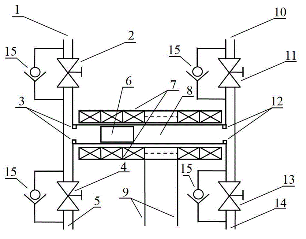
[0019] An H-bridge power generation device, including an H-bridge-type waterway pipeline, a permanent magnet piston (rotor) 6 and a stator coil 7; the H-bridge-type waterway pipeline includes a left bridge arm, a right bridge arm, and a bridge arm passage 8. The left bridge arm The two ends of the left bridge arm are the left bridge arm water inlet 1 and the left bridge arm water outlet 5, the right bridge arms are respectively the right bridge arm water inlet 10 and the right bridge arm outlet 14, and the left bridge arm water inlet 1 entrance The left bridge arm upper solenoid valve 2 is installed, the left bridge arm lower solenoid valve 4 is installed at the outlet of the left bridge arm water outlet 5, the right bridge arm upper solenoid valve 11 is installed at the entrance of the right bridge arm water inlet 10, and the right bridge The right bridge arm lower solenoid valve 13 is installed at the outlet of the arm water outlet 14; the left limit buffer device 3 and the ri...

Embodiment 2

[0023] The principle is the same as that in embodiment 1. A single-phase rectifier bridge is added at both ends of the stator coil outlet 9 and a larger capacitor is connected in parallel in the output section to obtain a DC voltage output; if the single-phase or three-phase inverter bridge is connected in series, single-phase or three-phase inverter bridges can be obtained. Phase alternating current, voltage and frequency can be adjusted as required.

Embodiment 3

[0025] The principle is the same as in Example 1. When the pipe diameter is increased to increase the water flow and output power, the left bridge arm upper solenoid valve 2, the left bridge arm lower solenoid valve 4, the right bridge arm upper solenoid valve 11, and the right bridge arm lower The solenoid valve 13 is replaced with an electric valve or other large flow control valve.


PUM


Abstract

The invention discloses a power generation method and device of an H-bridge. The device comprises an H-bridge-type waterway pipeline, a permanent magnetic piston (rotor) and a stator coil; the H-bridge-type waterway pipeline comprises a left bridge arm, a right bridge arm and a bridge arm channel; a left spacing buffer device and a right spacing buffer device are installed at two ends of the inner side of the bridge arm channel respectively; the permanent magnetic piston (rotor) is positioned in the bridge arm channel and is positioned within the spacing range of the left spacing buffer device and the right spacing buffer device; the stator coil is around the periphery of the outer surface of the bridge arm channel; and the stator coil is connected with a stator coil outgoing line. In power generation, through controlling four electromagnetic valves on the H-bridge arm in pairs, under the spacing of the permanent magnetic piston (rotor) by the left spacing buffer device and the right spacing buffer device, the permanent magnetic piston (rotor) moves in the bridge arm channel in a reciprocating mode, thus a magnetic field cuts the stator coil, and electricity energy is generated on the stator coil outgoing line. The power generation method and device of the H-bridge have the characteristics of less water using amount, high water energy utilization ratio, low cost and the like.

Description

Technical field [0001] The present invention relates to the field of generators, in particular to an H-bridge power generation method and device. Background technique [0002] At present, there is a shortage of fresh water resources in my country, and the available hydropower resources are depleted day by day. Depending on the current hydropower generation method, it is difficult to develop and utilize some hydropower resources with smaller capacity and lower water head. At the same time, it is difficult to break through the water energy utilization efficiency of traditional hydroelectric generating units, and reducing the kinetic energy of the water output is a way to further improve the water energy utilization efficiency. In addition, the power generation device for recovering the potential energy of wastewater from high-rise buildings is also blank. Summary of the invention [0003] The purpose of the present invention is to overcome the shortcomings existing in the prior art...

Claims


Application Information

Patent Timeline
Patent Type & Authority Applications(China)
IPC IPC(8): F03B13/00
Inventor 闫国琦陈润恩
Owner 台山市共荣食品有限公司
Why Eureka
Try Eureka