Charging system for electric vehicle

A charging system and electric vehicle technology, applied in electric vehicles, vehicle energy storage, vehicle components, etc.

Active Publication Date: 2012-10-24
HONDA MOTOR CO LTD
View PDF6 Cites 7 Cited by
  • Summary
  • Abstract
  • Description
  • Claims
  • Application Information

AI Technical Summary

Problems solved by technology

[0005] As described above, in Patent Document 1, the power supply lines L1 and L2 are provided between the charging port L1 and the drive battery 3 for charging, but if the power supply lines L1 and L2 are short-circuited for some reason and the main When the relays 5a and 5b are turned on (closed), a short-circuit current flows from the drive battery 3

Method used


Image

  • Charging system for electric vehicle
  • Charging system for electric vehicle
  • Charging system for electric vehicle

Examples


Embodiment Construction

[0043] 1. Description of the overall composition

[0044] [1-1. Overall composition]

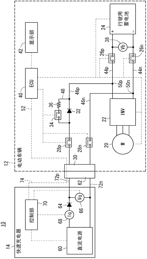
[0045] figure 1 It is a schematic configuration diagram of a charging system 10 of an electric vehicle 12 (hereinafter also referred to as "vehicle 12") according to an embodiment of the present invention. The charging system 10 includes a vehicle 12 and a quick charger 14 (hereinafter also referred to as "charger 14").

[0046] [1-2. Vehicle 12]

[0047] The vehicle 12 has a travel motor 20 (hereinafter also referred to as "motor 20"), an inverter 22, a travel battery 24 (hereinafter also referred to as "battery 24"), and main contactors 26p and 26n on the anode side and cathode side. , quick charging contactors 28p and 28n on the anode side and cathode side (hereinafter also referred to as “QCC28p and 28n”), vehicle-side connector 30 (vehicle-side charging connector), vehicle-side diode 32 (hereinafter also referred to as “diode 32"), bypass contactor 34 (hereinafter also referred to as ...


PUM


Abstract

The present invention provides a charging system for an electric vehicle, capable of preventing generation of a short-circuit current even if short circuit occurs at a vehicle side charging lead. A charging system (10) for an electric vehicle (12) is arranged on vehicle side charging leads (46p, 46n) between a vehicle side charging connector (30) and an electrical storage device (24), and has a diode (32) for preventing a backflow current from the electrical storage device (24) to a charging device (14).

Description

technical field [0001] The invention relates to charging systems for electric vehicles. Background technique [0002] A charging system for an electric vehicle is known (Patent Document 1). In Patent Document 1, when charging, the charging port 1 is connected to an external charger, and the drive battery 3 is charged from the external charger ( figure 1 , paragraphs [0009], [0010]). Charging port 1 is connected to driving battery 3 via power supply lines L1 , L2 between charging port 1 and driving battery 3 , and power supply lines L3 , L4 between inverter circuit 2 and driving battery 3 . Charging relays 4a, 4b are provided on the power supply lines L1, L2, and main relays 5a, 5b are provided on the power supply lines L3, L4 ( figure 1 , paragraph [0009]). During charging, the charging relays 4a and 4b are turned on (connected state), and the output of the external charger connected to the charging port 1 is supplied to the drive battery 3, thereby charging the drive ba...

Claims


Application Information

Patent Timeline
IPC IPC(8): H02J7/00H02H11/00H02H7/18B60L11/18
CPCY02E60/12Y02T10/7005Y02T10/7216Y02E60/10Y02T10/72
Inventor 佐佐木实鹰觜弘明长谷部哲也中岛昌俊岩下秀晓天野敦史出口真也
Owner HONDA MOTOR CO LTD
Why Eureka
Try Eureka