Apparatus for supplying electrical power to an electric motor

A technology for electric motors and energy transmission, which is applied in the field of electric motors to achieve the effect of improving energy efficiency

Inactive Publication Date: 2012-05-02
ROBERT BOSCH GMBH
View PDF1 Cites 0 Cited by
  • Summary
  • Abstract
  • Description
  • Claims
  • Application Information

AI Technical Summary

Problems solved by technology

However, in the case of high-current clocking, due to the always present lead inductance, voltage peaks or current peaks form, which can also adversely affect other vehicle components electromagnetically.

Method used


Image

  • Apparatus for supplying electrical power to an electric motor
  • Apparatus for supplying electrical power to an electric motor
  • Apparatus for supplying electrical power to an electric motor

Examples


Embodiment Construction

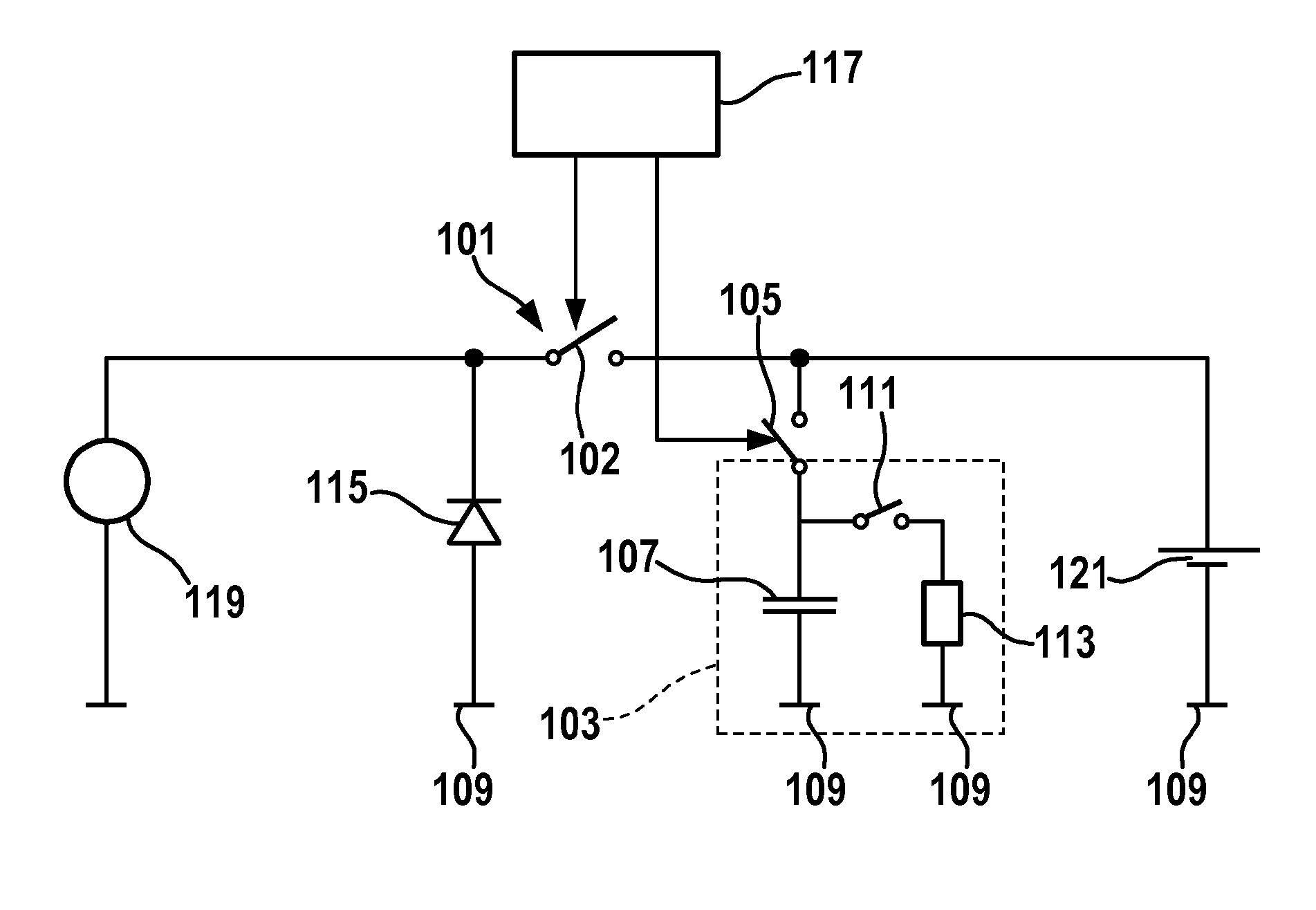
[0026] figure 1 A device for supplying electrical energy to an electric motor is shown. The device comprises: a first controllable switching device 101 , eg a switch; and a second controllable switching device 103 connecting an input of the first controllable switching device 101 to a switch 102 . The second controllable switching device 103 includes, for example, a controllable switch 105 , which is connected to a ground terminal 109 via a capacitor 107 , which can be, for example, a double-layer capacitor. A resistor 113 is arranged in a switchable manner parallel to capacitor 107 by means of a switch 111 . The device also includes a diode 115 arranged in the blocking direction, which connects the output of the controllable switching device 111 to the ground terminal 109 .

[0027] Furthermore, a control device 117 is provided, which controls the controllable switching devices 101 and 103 .

[0028] figure 1 The device shown in may, for example, connect an electric motor...


PUM


Abstract

The invention relates to an apparatus for supplying electrical power to an electric motor, having a first controllable switching arrangement (101), which is designed to provide a first current path to the power supply in a first switching state and interrupt the first current path in a second switching state, having a second controllable switching arrangement (103), which is coupled to the first controllable switching arrangement and is designed to provide a second current path for current consumption in a first switching state and to interrupt the second current path in a second switching state, and having a control device (117) for changing the first controllable switching arrangement (101) and the second controllable arrangement (103) to the first switching state or to the second switching state, with the control device (117); being designed to change the second switching arrangement (103) to the first switching state when or after the first switching arrangement (101) is changed to the second switching state.

Description

technical field [0001] The invention relates to the field of electric motors in vehicle drives. Background technique [0002] In modern hybrid drives with an internal combustion engine and another drive source such as an electric motor, the electric motor is also used as a starter to start the internal combustion engine. For this purpose, in particular the electrical components need to be sufficiently dimensioned, since high power and high currents are required to start the internal combustion engine. Thus, the peak current required by the starter can range from hundreds of amps up to 1000 amps or even more depending on the size of the vehicle's engine. These high currents are fed by the onboard grid or the starter battery in conventional onboard grid topologies, where the line resistivity and component internal resistances (such as those of the starter battery or starter) are often insufficient These high currents are ground-limited, which can lead to a pulse-like high cr...

Claims


Application Information

Patent Timeline
Patent Type & Authority Applications(China)
IPC IPC(8): H02P7/29F02N11/04F02N11/08H02J7/34
CPCB60L11/005Y02T10/7022F02N2011/0885F02N11/087Y02T10/642F02N11/0866H02J7/0063H02P7/29B60L50/40Y02T10/64Y02T10/70
Inventor W.米勒G.雷特曼M.默克勒M.阿贝勒
Owner ROBERT BOSCH GMBH
Why Eureka
Try Eureka